Manufacture method for semiconductor device

A manufacturing method and semiconductor technology, applied in semiconductor/solid-state device manufacturing, semiconductor devices, electrical components, etc., can solve problems such as reducing the reliability of high-k gate dielectrics, affecting the work function of metal gates, and affecting the electrical characteristics of devices. Effects of controlling, increasing selection ratio, and inhibiting growth

Active Publication Date: 2014-12-17
BEIJING YANDONG MICROELECTRONICS
View PDF5 Cites 0 Cited by
  • Summary
  • Abstract
  • Description
  • Claims
  • Application Information

AI Technical Summary

Problems solved by technology

It is characterized by a simple process and is compatible with the standard CMOS process. Some processes commonly used in the standard CMOS process can also be used in the gate-first process, which is beneficial to save costs, but this method has some insurmountable shortcomings: first, the metal gate The electrode is easily penetrated by the ions implanted into the source / drain to affect the electrical characteristics of the device. Secondly, the high-temperature process of activating the source / drain impurities will have a great impact on the work function of the metal gate. Most metal gate materials are processed after high-temperature annealing. Its work function will move to the center of the forbidden band, resulting in the degradation of device performance
The advantage of this gate-last process is that the metal gate electrode is formed after the source / drain activation thermal annealing process, which avoids the influence of the high-temperature process on the characteristics of the metal gate, enables the device to obtain high stability and consistency, and is conducive to the formation of high-performance High-k gate dielectric / metal gate semiconductor devices and circuits; but this gate-last process also has certain shortcomings, mainly because it is easy to cause damage to the underlying high-k gate dielectric when removing the dummy gate electrode, reducing the high-k gate dielectric reliability

Method used


Image

  • Manufacture method for semiconductor device
  • Manufacture method for semiconductor device
  • Manufacture method for semiconductor device

Examples


Embodiment Construction

[0012] Hereinafter, the present invention is described by means of specific embodiments shown in the drawings. It should be understood, however, that these descriptions are exemplary only and are not intended to limit the scope of the present invention. Also, in the following description, descriptions of well-known structures and techniques are omitted to avoid unnecessarily obscuring the concept of the present invention.

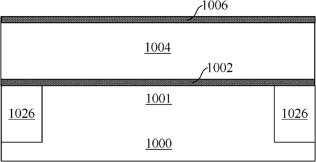
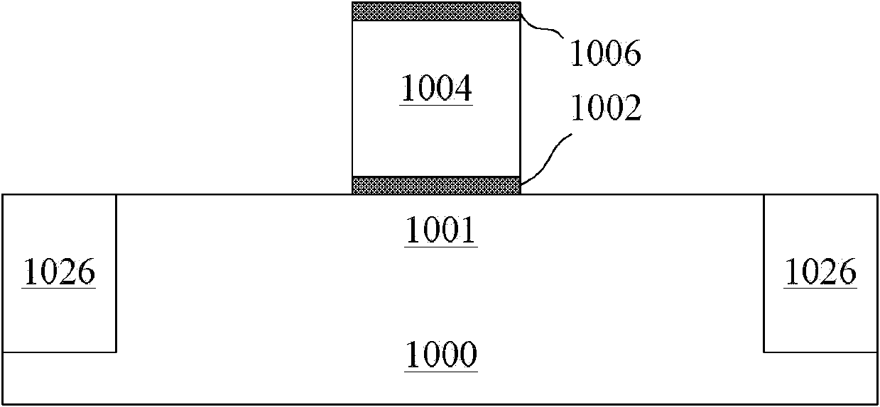
[0013] A schematic diagram of a layer structure according to an embodiment of the invention is shown in the drawing. The figures are not drawn to scale, with certain details exaggerated and possibly omitted for clarity. The shapes of the various regions and layers shown in the figure, as well as their relative sizes and positional relationships are only exemplary, and may deviate due to manufacturing tolerances or technical limitations in practice, and those skilled in the art will Regions / layers with different shapes, sizes, and relative positions can be...


PUM


Abstract

The invention discloses a manufacture method for a semiconductor device, which includes the steps: providing a semiconductor substrate; forming field-displacement on the semiconductor substrate prior to forming a sacrifice gate stack on the same; forming spacers surrounding the sacrifice gate stack; forming a source / drain region on two sides of the sacrifice gate stack; forming a SiO2 (silicon dioxide) layer on the semiconductor substrate, spinning SOG (spin on glass) on the SiO2 layer, and planarizing the sacrifice gate stack by means of reactive ion etching until the top of the sacrifice gate stack is exposed; and removing the sacrifice gate stack so that grooves are formed in the spacers, and forming a high-k gate dielectric / a metal gate stack in each groove.

Description

technical field [0001] The invention relates to the technical field of nano-semiconductor devices, in particular to a method for preparing a replacement gate of a semiconductor device with a high-k gate dielectric / metal gate structure. The method uses sacrificial SiO 2 / The polysilicon gate is used as a dummy gate, and after SOG planarization and reverse etching process, the sacrificial SiO is removed 2 / polysilicon dummy gate structure to form a high-k gate dielectric / metal gate stack. Background technique [0002] For more than 40 years, integrated circuit technology has continued to develop according to Moore's law, with continuous shrinking of feature size, continuous improvement of integration, and increasingly powerful functions. Currently, the feature size of metal-oxide-semiconductor transistors (MOSFETs) has entered sub-50 nanometers. With the continuous reduction of device feature size, if the traditional polysilicon gate is still used, the polysilicon depletion ...

Claims


Application Information

Patent Timeline
Patent Type & Authority Patents(China)
IPC IPC(8): H01L21/28H01L21/336H01L21/316
Inventor 许高博徐秋霞
Owner BEIJING YANDONG MICROELECTRONICS
Why Eureka
Try Eureka