Mobile communication terminal intenna using a electrically conductive film and the manufacturing method thereof

A technology with built-in antenna and conductive film, applied in the direction of antenna support/installation device, radiating element structure, etc., can solve the problems of copper and other conductive materials damage, increase manufacturing cost, and cumbersome manufacturing process, so as to reduce manufacturing cost. , The effect of improving production efficiency and simplifying the manufacturing process

Inactive Publication Date: 2012-07-04
卢东镐 +2
View PDF5 Cites 3 Cited by
  • Summary
  • Abstract
  • Description
  • Claims
  • Application Information

AI Technical Summary

Problems solved by technology

[0006] However, the manufacturing process of the flexible printed circuit board built-in antenna in the above-mentioned prior art is very complicated when forming the built-in antenna pattern. As mentioned above, not only the dry film processing process is required, but also the conductive body needs to be punched and cut on the above-mentioned negative film. In addition, the exposure process, drying process, and washin

Method used


Image

  • Mobile communication terminal intenna using a electrically conductive film and the manufacturing method thereof
  • Mobile communication terminal intenna using a electrically conductive film and the manufacturing method thereof
  • Mobile communication terminal intenna using a electrically conductive film and the manufacturing method thereof

Examples


Embodiment Construction

[0028] In the following, the present invention will be described in detail with reference to the accompanying drawings of the present invention in combination with the purpose and features of the present invention.

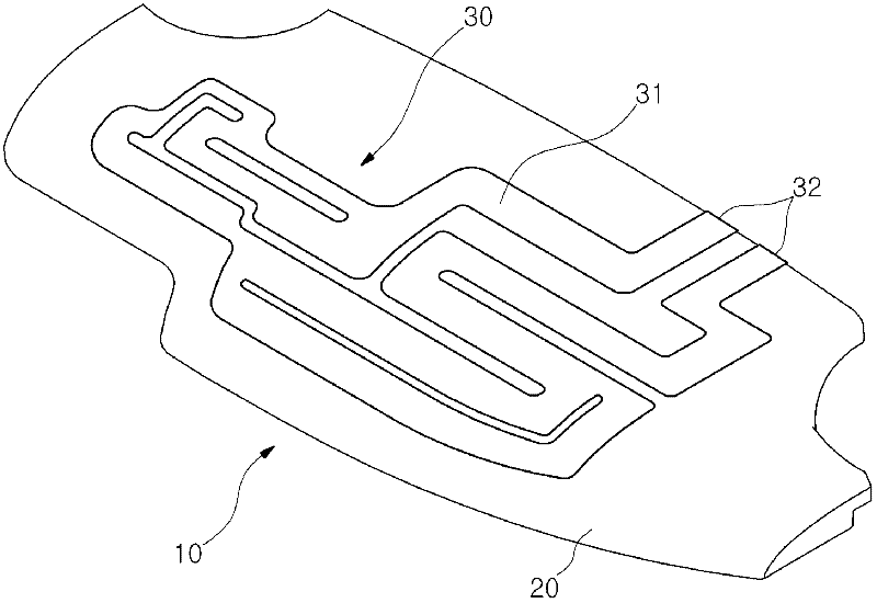
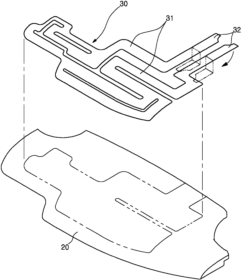
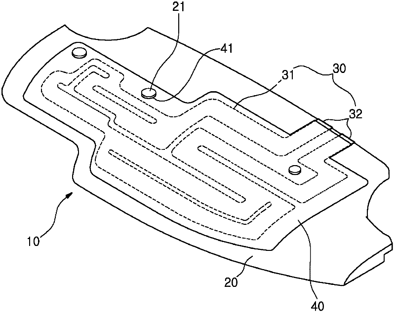
[0029] figure 1 is a perspective view of an embodiment of the present invention; figure 2 It is an exploded perspective view of an embodiment of the present invention; image 3 is a perspective view of another embodiment of the present invention; Figure 4 is an exploded perspective view of another embodiment of the present invention; Figure 5 It is an engineering flow chart of the manufacturing engineering of an embodiment of the present invention; Image 6 is the manufacturing engineering drawing of the present invention in a real-time manner; Figure 7 It is an engineering flow chart of the manufacturing engineering in another embodiment of the present invention; Figure 8 is a manufacturing engineering drawing of another embodiment of the present invent...


PUM


Abstract

An antenna for a radio communication terminal using a conductive film and a manufacturing method thereof are provided to drastically improve productivity and to offer convenience of manufacture by a simple manufacturing process and to reduce manufacture costs. An antenna main body(20) is composed of plastic. A thin film conductor(30) comprises antenna pattern(31) and a contacting portion(32). The antenna pattern is located in the front of the antenna main body. The thin film conductor is formed after punching a conductive film including copper foil consisting of conductive materials in order to form the antenna pattern and the contacting portion as one body. The thin film conductor is adhered in the antenna main body by adhesive.

Description

technical field [0001] The present invention relates to a built-in wireless communication antenna using a conductive film and a manufacturing method thereof. The built-in wireless communication antenna using a conductive film and a manufacturing method thereof of the present invention provide convenient manufacturing and can greatly improve Productivity. Background technique [0002] Generally speaking, wireless communication terminals such as mobile phones, PDAs, and tablet computers can be carried by users, and they can browse the Internet, watch videos or use online games at any time, and can also be used for calls. Antenna for picking up voice or video signals. [0003] The above-mentioned antenna is usually an external antenna protruding from the terminal body to improve the performance of sending and receiving signals. Due to the harmfulness of electromagnetic waves, low performance of sending and receiving signals, and high power consumption, this external antenna ha...

Claims


Application Information

Patent Timeline
IPC IPC(8): H01Q1/12H01Q1/38
Inventor 卢东镐申东元卢承奕
Owner 卢东镐
Why Eureka
Try Eureka