Sectional rotor structure for permanent magnet synchronous motor

A permanent magnet synchronous motor, rotor structure technology, applied in the magnetic circuit shape/style/structure, magnetic circuit rotating parts, magnetic circuit and other directions, can solve the problem of unsuitable motors, bending of positioning tension bolts, occupying the effective length of the rotor and other problems, to achieve the effect of not easy to break, avoid magnetic leakage, and long service life

Active Publication Date: 2012-07-04
ZHEJIANG UNIV
View PDF9 Cites 9 Cited by
  • Summary
  • Abstract
  • Description
  • Claims
  • Application Information

AI Technical Summary

Problems solved by technology

[0008] This kind of permanent magnet motor rotor has the following disadvantages: 1. The centrifugal force on the rotor pole piece is jointly borne by the end plate, the partition plate and the positioning tension bolts, that is to say, the positioning tension bolts that fix the rotor unit need to bear the bending moment. When the rotor When rotating at high speed, the centrifugal force is very large, which may easily cause the positioning and tension bolts to be bent by centrifugal force, that is to say, the rotor is not suitable for high-speed rotating motors.
2. Although there is a magnetic separation groove in the iron core, there are still connecting parts between the iron cores between

Method used


Image

  • Sectional rotor structure for permanent magnet synchronous motor
  • Sectional rotor structure for permanent magnet synchronous motor
  • Sectional rotor structure for permanent magnet synchronous motor

Examples


Example Embodiment

[0034] Embodiment one

[0035] refer to Figure 1-5

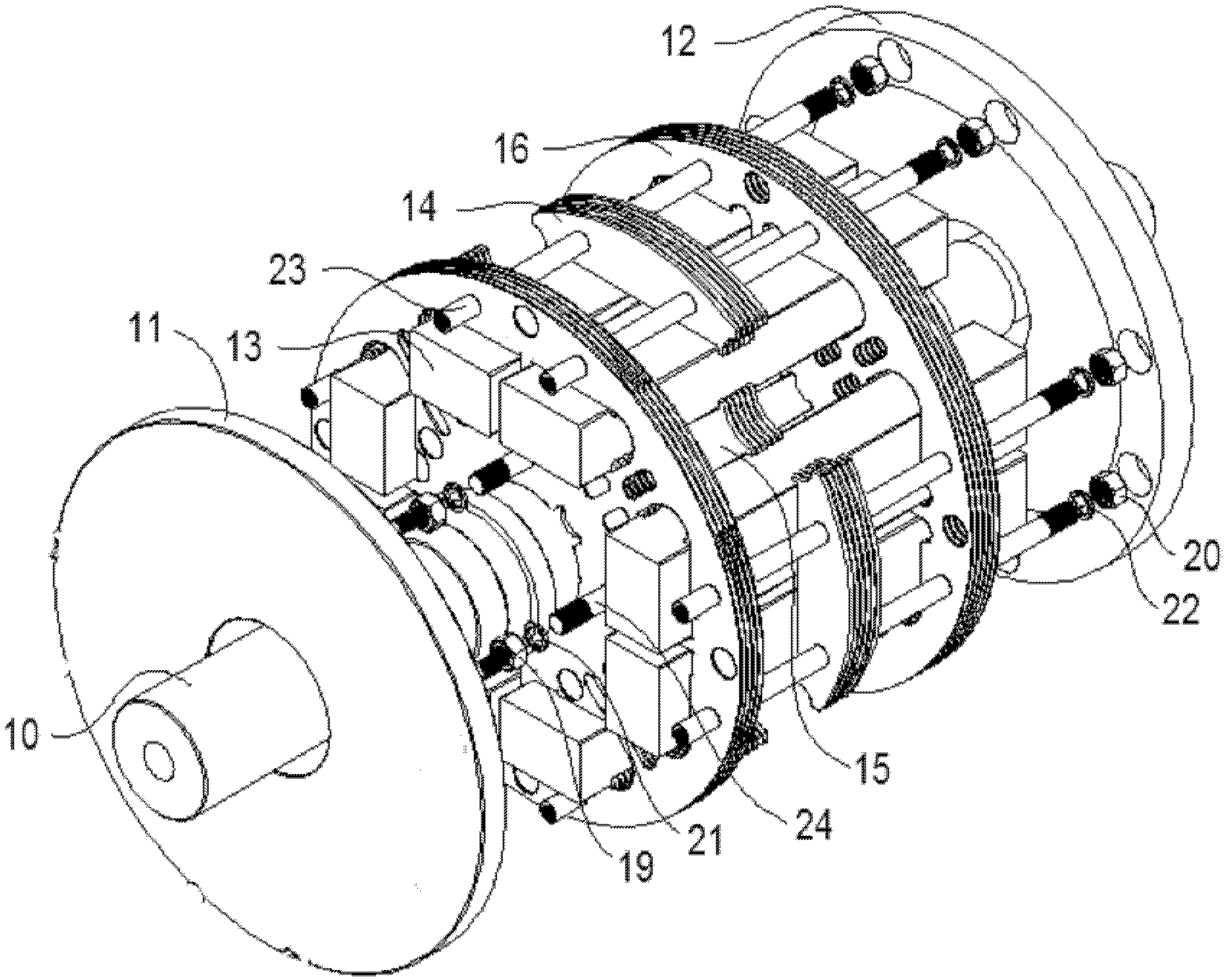
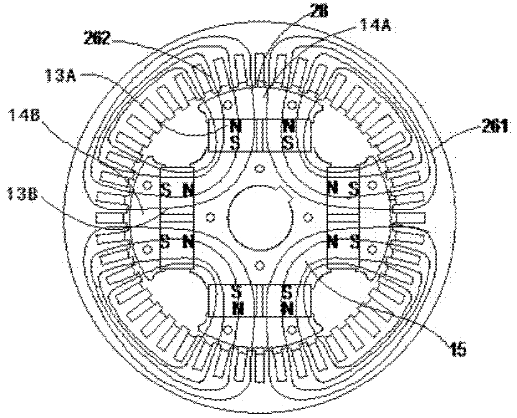
[0036] like figure 1As shown, the rotor structure of the segmented permanent magnet synchronous motor includes a rotating shaft 10, a rotor core 15 fixed on the rotating shaft 10, a permanent magnet 13 sleeved outside the rotor core 15, and located outside the permanent magnet 13 for reasonable distribution of the magnetic field and permanent magnetism. The rotor pole piece 14 for protection by the magnet 13, and the front end plate 11 and the rear end plate 12 respectively located at both ends of the rotor core 15;

[0037] A plurality of rotor diaphragms 16 made of non-magnetic conductive materials are arranged between the two end plates 11 and 12, the rotor pole pieces 14 are independent of each other, and the rotor pole pieces 14 and the rotor diaphragm 16 are distributed at intervals in the axial direction. The rotor diaphragm 16 divides the rotor into a plurality of rotor units in the axial direction. The two end f...

Example Embodiment

[0048] Embodiment 2

[0049] refer to Figure 6-12

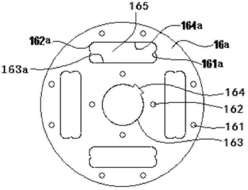
[0050] The difference between this embodiment and the first embodiment is that the rotor diaphragm 16 is provided with a weight-reducing hole. The rotor diaphragm 16 is provided with weight reduction holes 166 for reducing the weight of the diaphragm and reducing stress concentration. A plurality of weight reduction holes 166 are distributed around each permanent magnet through hole 165, and a plurality of weight reduction holes 166 around the same permanent magnet 13 The holes 166 form a group of weight-reduction holes, which are symmetrically distributed among the groups of weight-reduction holes. The weight-reducing holes 166 are circular holes or waist-shaped holes or polygonal holes whose corners are arc transitions, and the weight-reducing holes 166 are mainly concentrated at the corners of the permanent magnet through holes.

[0051] The structure of the third rotor diaphragm 16c is as follows Image 6 As shown, t...

Example Embodiment

[0057] Embodiment 3

[0058] refer to Figure 13

[0059] The difference between this embodiment and the second embodiment is that pole shoe tightening nuts 20 are respectively provided at both ends of the pole shoe tightening bolt 23, and the pole shoe tightening nuts 20 are in close contact with the rotor pole shoes 14 at both ends; The two ends of the tightening bolt 20 are respectively provided with fixed screw holes. The front end plate 11 and the rear end plate 12 are respectively connected to the pole shoe tightening bolts 23 through screws 18 which engage with the fixed screw holes. The rest of the structure is the same.

[0060] The front end plate 11 and the rear end plate 12 of the rotor are made of thicker non-magnetically conductive material (such as high-strength aluminum alloy) or low-permeability material (such as high-strength austenitic stainless steel), which not only affects the rotor pole piece 14, The rotor diaphragm 16 and the permanent magnets 13 hav...


PUM

PropertyMeasurementUnit
Thicknessaaaaaaaaaa

Abstract

A sectional rotor structure for a permanent magnet synchronous motor comprises a rotating shaft, a rotor core, permanent magnets, rotor pole shoes, a front end-plate and a rear end-plate, wherein a plurality of rotor baffles are arranged between the two end-plates; the rotor pole shoes are independent of one another and axially distributed at intervals together with the rotor baffles; the rotor baffles divide axially a rotor into a plurality of rotor units; two end surfaces of the rotor pole shoes in each rotor unit are respectively clung to the end surfaces of the adjacent rotor baffles; the rotor pole shoes in each rotor unit correspond to the permanent magnets; through holes allowing the permanent magnets to penetrate are formed on the rotor baffles; pole shoe draw-in bolts penetrate the front end-plate, the rotor pole shoes, the rotor baffles and the rear end-plate and axially lock the rotor pole shoes and the rotor baffles, which are arranged between the front and the rear end-plates; and the corners of the through holes of the rotor baffles are in arc transition, and clearances are kept between the permanent magnets and the permanent-magnet through holes on the rotor baffles. The sectional rotor structure for the permanent magnet synchronous motor has the advantages of high mechanical strength and suitability for motors rotating at high speed.

Description

technical field [0001] The invention relates to a rotor structure of a radial permanent magnet synchronous motor, in particular to a permanent magnet built-in segmented permanent magnet synchronous motor rotor for a permanent magnet traction motor of a high-speed railway train. Background technique [0002] The motor is an electromagnetic device that converts mechanical energy and electrical energy through the medium of a magnetic field. In order to establish the air-gap magnetic field necessary for electromechanical energy conversion inside the motor, there are two methods. One is to pass current through the motor windings to generate a magnetic field, such as ordinary DC motors and electric motors. This kind of electrically excited motor not only needs to have special windings and corresponding devices, but also needs to be continuously supplied with energy to maintain the current flow; the other is to generate a magnetic field by a permanent magnet. Due to the inherent ...

Claims


Application Information

Patent Timeline
IPC IPC(8): H02K1/27
CPCH02K1/27H02K1/276
Inventor 方攸同马子魁卢琴芬黄晓艳马吉恩张建承陈威
Owner ZHEJIANG UNIV
Why Eureka
Try Eureka