In-system programming universal PFC multifunctional processor

A technology of processors and DC converters, applied in instruments, climate sustainability, output power conversion devices, etc., can solve the problems of poor versatility of PFC modules, achieve the effects of reducing sampling points, simplifying the processing process, and reducing EMI

Inactive Publication Date: 2014-05-14
深圳市益力盛电子有限公司
View PDF6 Cites 0 Cited by
  • Summary
  • Abstract
  • Description
  • Claims
  • Application Information

AI Technical Summary

Problems solved by technology

[0007] In order to overcome the deficiencies of the prior art, the present invention provides a PFC processor implemented by a general-purpose chip and an embedded method, which reduces the sampling circuit of the system, solves the problem of poor versatility of the PFC module in the power drive system, and increases the online programmable function. Reduce system EMI and improve practical performance

Method used


Image

  • In-system programming universal PFC multifunctional processor
  • In-system programming universal PFC multifunctional processor
  • In-system programming universal PFC multifunctional processor

Examples


no. 1 example

[0036] see Figure 5 According to the conception of this case and the first example realized based on the BOOST step-up converter, it mainly includes mains input, full-wave rectifier bridge BD, inductor L1, inductor current sampling circuit, power switch tube Q1, steering diode D1, capacitor C1 , Output voltage sampling circuit, load resistor R and PFC processor. The live line L of the mains is connected to the AC input terminal AC+ of the rectifier bridge BD; the neutral line N of the mains is connected to the AC- terminal of the rectifier circuit; one end of the inductor L1 is connected to the DC input end DC+ of the rectifier bridge BD, and the other end is connected to the power The drain of the switching tube Q1 and the anode of the steering diode D1; the source of the switching tube Q1 is connected to one end of the current sampling resistor R1, and the gate of the switching tube is connected to the port I / O.0 of the main control microcontroller; the other end of the cur...

no. 2 example

[0040] see Figure 6 According to the concept of this case and based on the BUCK step-down converter, the second example mainly includes mains input, full-wave rectifier bridge BD, power switch tube Q1, diversion diode D1, inductor L1, capacitor C1, load resistor R, Output voltage sampling circuit, inductor current sampling circuit and PFC processor. The live line L of the mains is connected to the AC input terminal AC+ of the rectifier bridge BD; the neutral line N of the mains is connected to the AC- terminal of the rectification circuit; The cathode of the diode D is connected to one end of the inductor L1, and the gate is connected to the port I / O.0 of the main control microcontroller; the anode of the diode D is connected to the current sampling resistor R1; the other end of the current sampling resistor R1 is connected to the rectifier bridge BD The DC-end is connected; the other end of the inductor L1 is connected to the capacitor C1, one end of the resistor R2a, and o...

no. 3 example

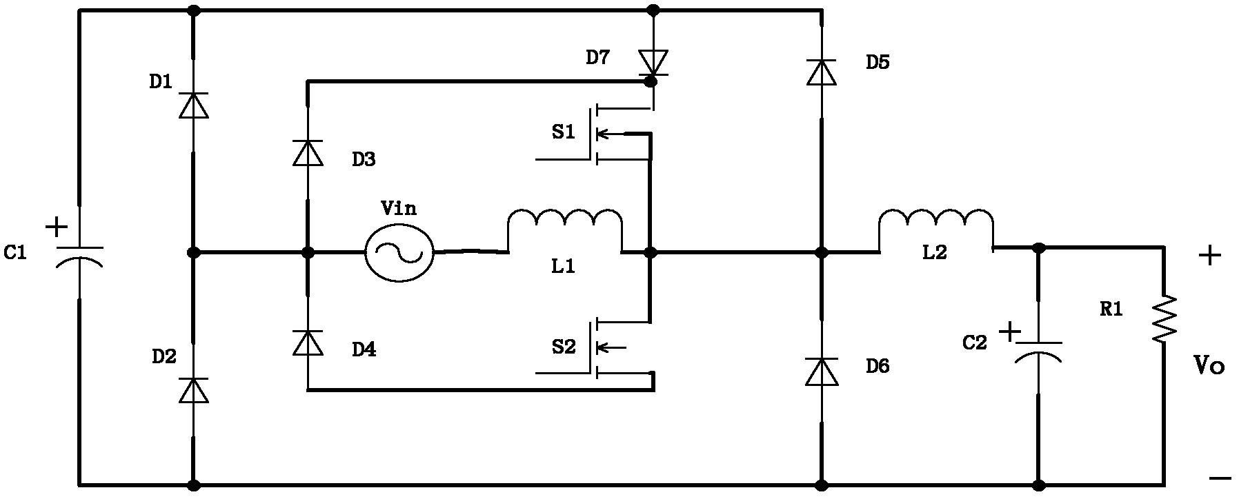
[0044] see Figure 7 According to the concept of this case and based on the BOOST / BUCK buck-boost converter, the third example mainly includes mains power, full-wave rectifier bridge BD, power switch tube Q1, inductor L1, steering diode D1, capacitor C1, output voltage Sampling circuit, LED load, inductor current sampling circuit and PFC processor. The live line L of the mains is connected to the AC input terminal AC+ of the rectifier bridge BD; the neutral line N of the mains is connected to the AC- terminal of the rectification circuit; The cathode of the diode D is connected to one end of the inductor L1, and the gate is connected to the port I / O.0 of the main control microcontroller; the other end of the inductor L1 is connected to one end of the current sampling resistor R1; the other end of the sampling resistor R1 is connected to the rectifier The DC-end of the bridge BD is connected; the anode of the reverse flow diode D is connected to one end of the capacitor C1, on...


PUM


Abstract

The invention discloses an in-system programming universal PFC (Power Factor Correction) multifunctional processor. The multifunctional processor comprises full-wave rectification circuit, a DC / DC converting circuit and a PFC processor, and is characterized in that the full-wave rectification circuit converts AC commercial power into DC, the DC is output by a DC / DC converter, and the DC / DC converter is controlled by the PFC processor. The in-system programming universal PFC multifunctional processor has a simple and convenient processing procedure, and does not need frequent modification of hardware circuits; the various main-control MCU chips are adopted, the secondary development technology is easy to master, and the extensible functions are rich, so that EMI (Electromagnetic Interference) in the circuit can be effectively reduced.

Description

technical field [0001] The present invention relates to a processor for power factor correction (PFC). Background technique [0002] The PFC module technology currently used in power drivers is generally divided into two categories, one is to improve the structure of the existing basic circuit to achieve the effect of improving the power factor, such as the patent application number 201010607182. BUCK integrated bridgeless single-stage PFC circuit"; the other is to use a control chip specially used for rectification power factor correction, such as the CS1600 chip of Cirrus Logic Company, the PFC switching power supply control IC MM3460 for LED lights of MITSUMI Company, Marvell Company 88EM8080 / 81 and so on. [0003] For the first technique, implementing a circuit such as figure 1 As shown, it is characterized in that: through the power MOSFET tube S 1 , storage capacitor C 1 and diode D 7 Combining a bridgeless BOOST circuit and a BUCK circuit, the power MOSFET tube S...

Claims


Application Information

Patent Timeline
Patent Type & Authority Patents(China)
IPC IPC(8): H02M1/42H02M3/155
CPCY02B70/126Y02B70/10
Inventor 贺宏锟阳金金石雷王林博
Owner 深圳市益力盛电子有限公司
Why Eureka
Try Eureka