
Bidirectional power source of small spherical Tokamak ohm magnet

A tokamak and ohmic magnet technology, applied in the field of magnetic confinement fusion, can solve the problems of short life, surrounding environment interference, bulky absorption and buffer circuits, etc., and achieve the effect of reducing requirements, reducing electromagnetic interference, and working reliably

Active Publication Date: 2012-07-04
TSINGHUA UNIV
View PDF0 Cites 6 Cited by
  • Summary
  • Abstract
  • Description
  • Claims
  • Application Information

AI Technical Summary

Problems solved by technology

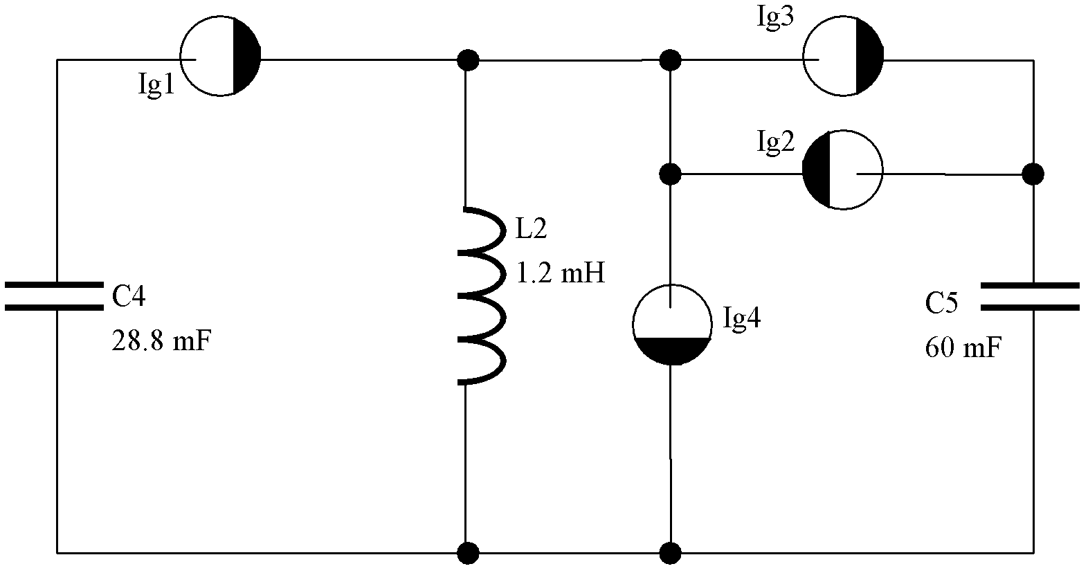
The main disadvantages of this circuit: the ignition tube used as a switch is a non-solid component with short life, mercury, and needs maintenance; the trigger sequence and reliability of the four high-current switches must be strictly guaranteed, otherwise it will lead to serious accidents, such as: work During the process, if the second switch Ig2 is not turned on normally, a very high induced voltage will be generated on the second magnetic field coil L2; if the third ignition tube Ig3 and the fourth ignition tube Ig4 are opened in advance, it will cause the fourth Capacitor C4 and fifth capacitor C5 are short-circuited
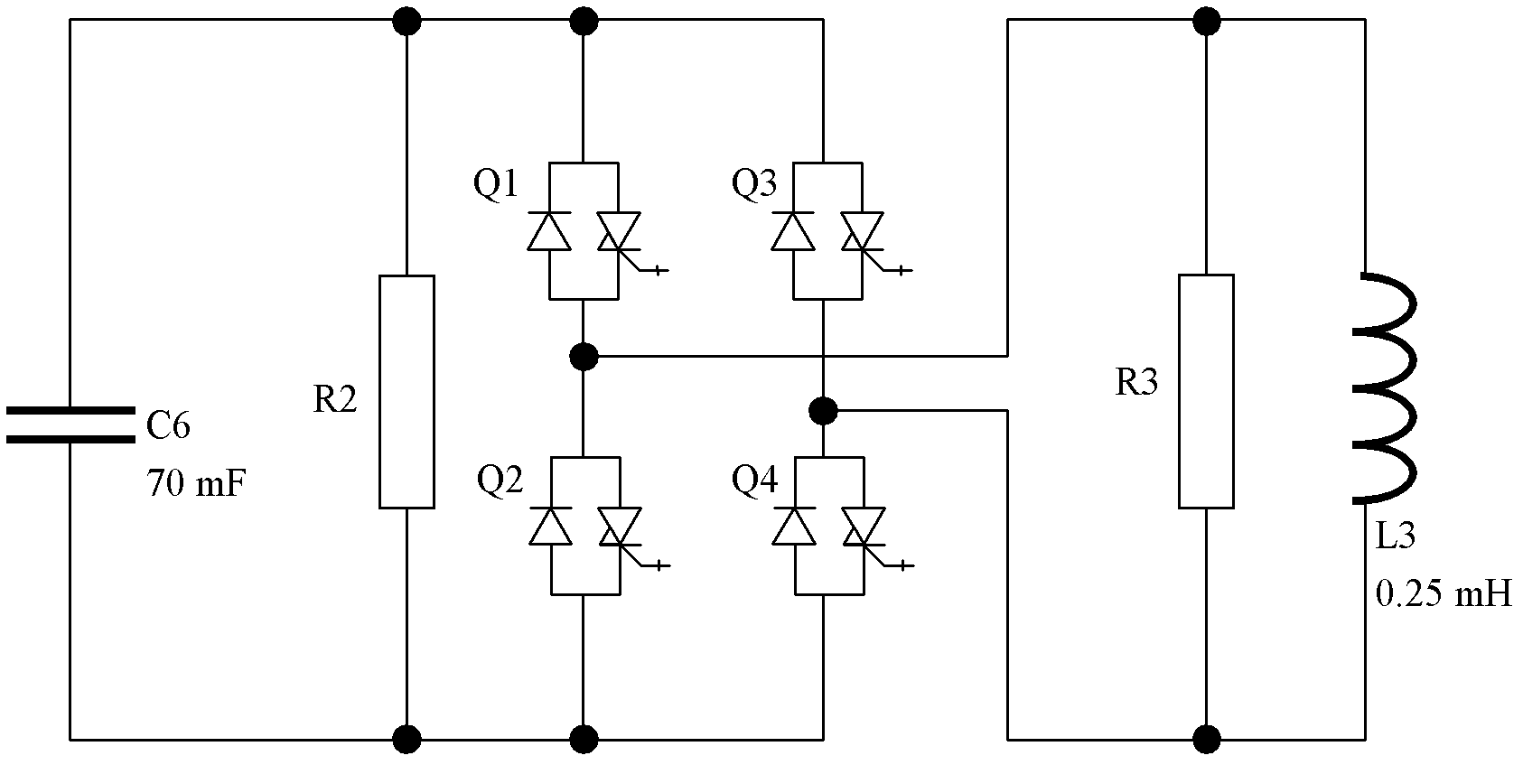
The main disadvantage of this circuit: only one group of capacitors are used for power supply, and four high-current switches must be turned on and off at high frequency by adjusting the duty cycle to achieve waveforms with different rates of change; Frequent switching on and off not only brings great interference to the surrounding environment, but also requires the use of a bulky absorption and buffer circuit (consisting of the second resistor R2 and the third resistor R3), and also increases the technology of equalizing the current of each parallel IGCT difficulty

Method used


Image

  • Bidirectional power source of small spherical Tokamak ohm magnet
  • Bidirectional power source of small spherical Tokamak ohm magnet
  • Bidirectional power source of small spherical Tokamak ohm magnet

Examples


Embodiment Construction

[0021] The preferred embodiments will be described in detail below in conjunction with the accompanying drawings. It should be emphasized that the following description is only exemplary and not intended to limit the scope of the invention and its application.

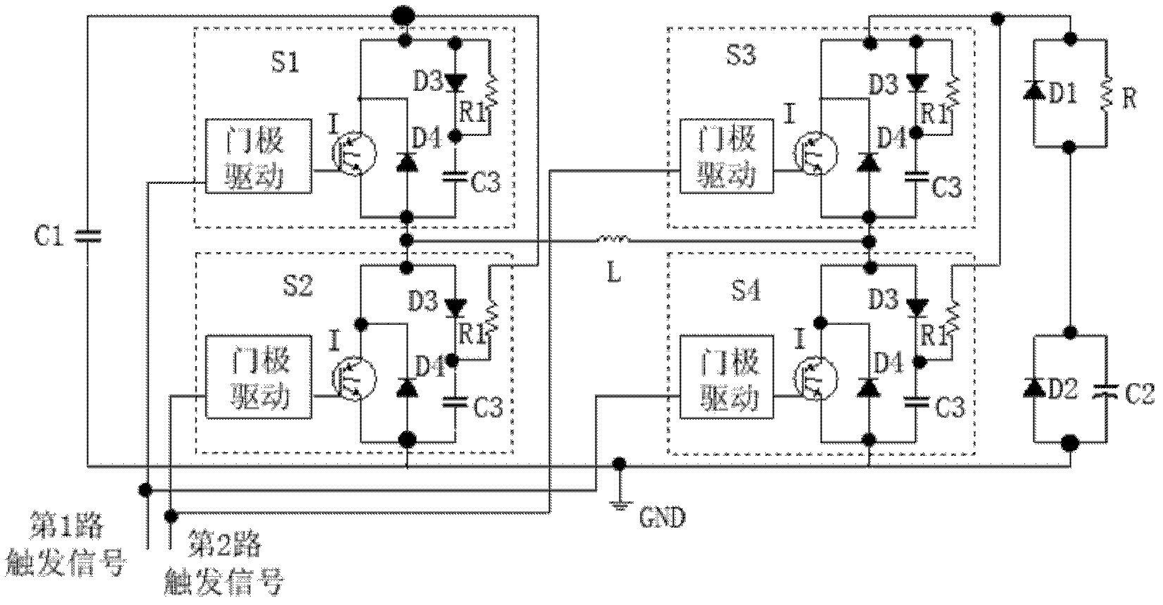
[0022] Such as image 3 As shown, the structure of the bidirectional power supply of the small spherical Tokamak ohmic magnet is as follows: the positive pole of the first capacitor bank C1 is respectively connected to the absorbing resistor R1 of the second IGBT switch module S2 and the collector of the IGBT device I of the first IGBT switch module S1 and the absorption resistor R1 of the first IGBT switch module S1, and the ground potential of GND are respectively connected to the negative pole of the first capacitor bank C1, the positive pole of the second diode D2, the negative pole of the second capacitor bank C2 and the opposite pole of the fourth IGBT switch module S4 The anode of the parallel diode D4, one end...


PUM


Abstract

The invention discloses a bidirectional power source of a small spherical Tokamak ohm magnet, belonging to the technical field of magnetic confinement fusion. The bidirectional power source consists of two capacitor groups, four IGBT (Insulated Gate Bipolar Transistor) switch modules, two diodes, a large-power non-inductive resistor and a first magnetic field coil. The bidirectional power source disclosed by the invention has the advantages that by using the four parallel-connected IGBT switch modules as a large-current (100 kA) switch, the bidirectional power source has the characteristics of simple and compact structure, convenience for driving, reliability in working and free maintenance; a waveform has no need of being adjusted by changing duty ratio, and the interference brought by frequently switching with a large current is eliminated; and the technical requirement on parallel connection of the IGBT switch modules is greatly reduced by only switching on and off the four IGBT switch modules once, so that the reliability is further improved.

Description

technical field [0001] The invention belongs to the technical field of magnetic confinement fusion, in particular to a bidirectional power supply for a small spherical tokamak ohmic magnet, in particular to a bidirectional power supply suitable for a small spherical tokamak air core ohmic magnet. Background technique [0002] The main function of the tokamak ohmic magnet is to generate a changing magnetic field, induce a toroidal electric field, break down the gas, heat the plasma and drive the toroidal plasma current. The time integral of the hoop voltage provided by an ohmic magnet is called volt-seconds, which is a major indicator of the performance of an ohmic magnet. Volt-seconds depend on how much the magnetic field changes. In most current tokamak devices, in order to make full use of the current capacity of the ohmic magnet coil, the coil current can swing from a positive maximum allowable value to a negative maximum allowable value, that is, bidirectional discharge...

Claims


Application Information

Patent Timeline
IPC IPC(8): H02M3/07
Inventor 谭熠高喆杨桂香解丽风王文浩王龙杨宣宗冯春华
Owner TSINGHUA UNIV
Learn More