Bearingless synchronous reluctance motor decoupling control system and construction method thereof

A synchronous reluctance motor and decoupling control technology, applied in control systems, vector control systems, motor generator control, etc., can solve problems such as poor motor transient response, motor flux linkage orientation, and increased implementation difficulty.

Active Publication Date: 2012-07-04
江苏扬先科技有限公司
View PDF8 Cites 11 Cited by
  • Summary
  • Abstract
  • Description
  • Claims
  • Application Information

AI Technical Summary

Problems solved by technology

[0004] After searching existing documents and patents, it was found that Michioka C et al. proposed "A Decoupling control method of reluctance-type bearingless motors considering magnetic saturation" (IEEE Trans.on Industry Applications, 1996, 32(5): 1204-1210 ), Zhang Hannian and others proposed "Decoupling Control of Bearingless Synchronous Reluctance Motor Based on Feedforward Compensator" (Journal of Southeast University, Natural Science Edition, 2005, Vol.35 Sup(II): 193-197) and "Bearingless Synchronous reluctance motor decoupling integrated control strategy" (Electric Transmission, 2009, Vol.39(9): 56-59), the above decoupling strategy adopts feedforward compensation and feedback decoupling methods, but there is no flux linkage to the motor Orientation, the dynamic performance is poor; in addition, Zhang Hannian and others applied for the national invention patent (applica

Method used


Image

  • Bearingless synchronous reluctance motor decoupling control system and construction method thereof
  • Bearingless synchronous reluctance motor decoupling control system and construction method thereof
  • Bearingless synchronous reluctance motor decoupling control system and construction method thereof

Examples


Embodiment Construction

[0063] In order to make the content of the present invention more comprehensible, further description will be made below in conjunction with the accompanying drawings and specific embodiments.

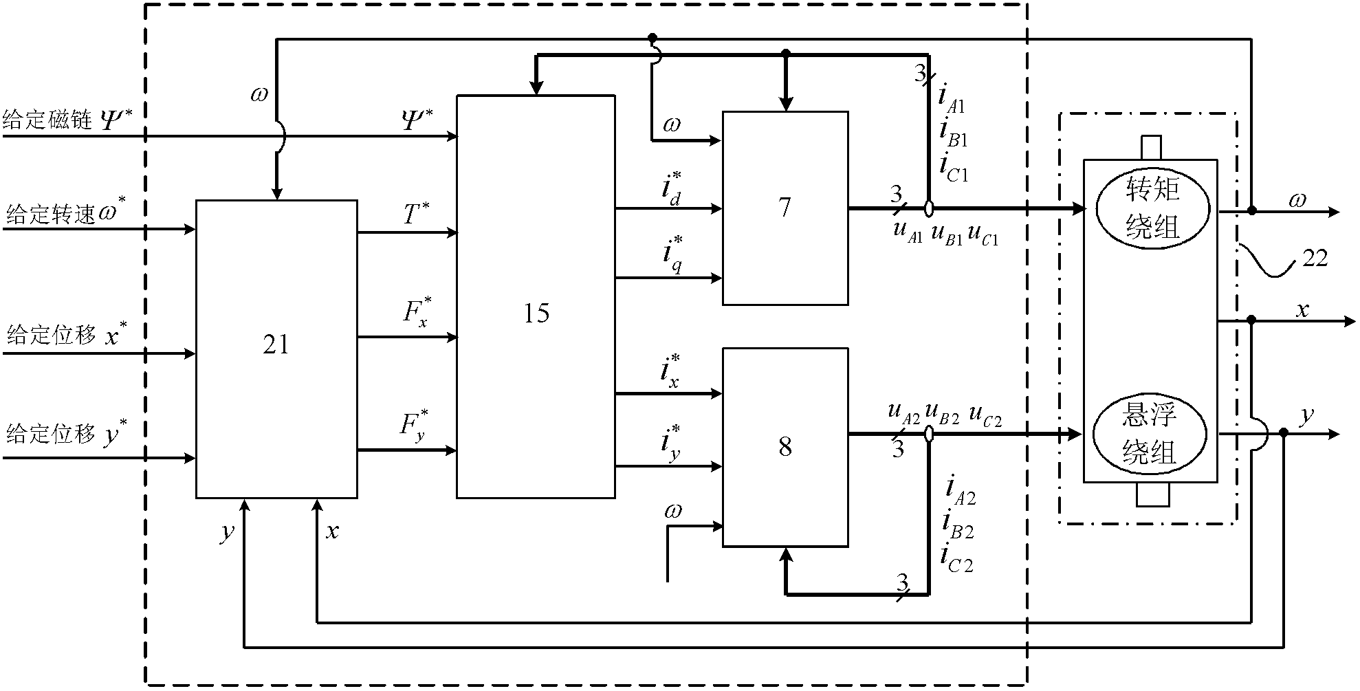
[0064] combine figure 1 , the bearingless synchronous reluctance motor decoupling control system of the present invention includes an expanded closed-loop regulator 21, a field-oriented decoupling model 15 and two expanded SVPWM inverters 7, 8, wherein:

[0065] Such as Figure 4 As shown, the extended closed-loop regulator 21 is composed of a closed-loop regulator 19 and a unilateral magnetic pull compensation model 20; the closed-loop regulator 19 is based on the given displacement, detected displacement, given rotational speed and detected rotational speed in the two-axis direction of the rotor as Input signal, output torque given value and two hybrid levitation force components; unilateral magnetic pull force compensation model 20 takes the detected displacement on the two-axis di...


PUM


Abstract

The invention discloses a bearingless synchronous reluctance motor decoupling control system and a construction method thereof, which are used for suspension and speed control. When the system is used, an extended SVPWM (space vector pulse width modulation) inverter is firstly constructed to supply power for a motor torque winding and a suspension winding; then a magnetic field oriented decoupling model is constructed to realize the decoupling control of the motor before the magnetic field oriented decoupling model is concatenated to the extended SVPWM inverter; and finally an extended closed loop regulator is designed to realize high-performance closed-loop control on the system. According to the system provided by the invention, the extended closed loop regulator and the magnetic field oriented decoupling model can be realized by using a digital signal processor (DSP); besides, the system also comprises a displacement and current sensor and a photoelectric decoder which are used for acquiring current, displacement and a rotor location angular signal required by analysis and control of the DSP. The system and the method provided by the invention are used for the decoupling control of the bearingless synchronous reluctance motor with simple algorithm and excellent performance.

Description

technical field [0001] The invention relates to a bearingless synchronous reluctance motor decoupling suspension operation control technology, which belongs to the technical field of electric power transmission equipment, in particular to a bearingless synchronous reluctance motor decoupling control system and a construction method thereof. Background technique [0002] Bearingless synchronous reluctance motor is a new type of AC motor with both levitation and rotation functions realized by power electronics technology and microprocessor control technology. Suspended levitation windings and torque windings for generating electromagnetic torque. The new motor has outstanding performance: ultra-high speed, no wear, no lubrication, etc. Compared with other types of bearingless motors (mainly induction type, permanent magnet type and switched reluctance type), the bearingless synchronous reluctance motor has control Simple, solid and reliable rotor, suitable for places with har...

Claims


Application Information

Patent Timeline
IPC IPC(8): H02P21/14H02P27/06H02P21/08H02P25/08H02P27/08
Inventor 张汉年张磊孙刚鲍安平张照锋
Owner 江苏扬先科技有限公司
Why Eureka
Try Eureka