Decoupling method and control device for suspension force feed-forward compensation of bearingless permanent magnet synchronous motor

A technology of permanent magnet synchronous motor and feedforward compensation, which is applied in the direction of motor generator control, electromechanical transmission control, electronic commutation motor control, etc. It can solve the problem of poor robustness, slow dynamic response, Problems such as increased difficulty in project realization

Inactive Publication Date: 2011-12-28
NANJING COLLEGE OF INFORMATION TECH
View PDF2 Cites 15 Cited by
  • Summary
  • Abstract
  • Description
  • Claims
  • Application Information

AI Technical Summary

Problems solved by technology

[0004] After searching the existing patents and documents, it was found that Fei Decheng and others proposed "Research on decoupling control of bearingless permanent magnet synchronous motor based on inverse system theory" (China Engineering Science, Vol. 7, No. 11, 2005, No. 48 pages to 54 pages), Sun Yukun and others proposed "Based on α-order inverse system five degrees of freedom bearingless permanent magnet motor decoupling control" (Proceedings of the Chinese Society for Electrical Engineering, 2006, Vol. Page), the above-mentioned decoupling control adopts the analytical inverse system method that completely depends on the precise model of the controlled motor, which is less robust to motor parameter changes and load disturbances; Sun Xiaodong et al. applied for the "Neural Network Generalized Inverse Bearingless Permanent magnet synchronous motor decoupling controller construction method" national invent...

Method used


Image

  • Decoupling method and control device for suspension force feed-forward compensation of bearingless permanent magnet synchronous motor
  • Decoupling method and control device for suspension force feed-forward compensation of bearingless permanent magnet synchronous motor
  • Decoupling method and control device for suspension force feed-forward compensation of bearingless permanent magnet synchronous motor

Examples


Embodiment Construction

[0053] In order to make the content of the present invention more obvious and understandable, further description will be given below in conjunction with the accompanying drawings and specific embodiments.

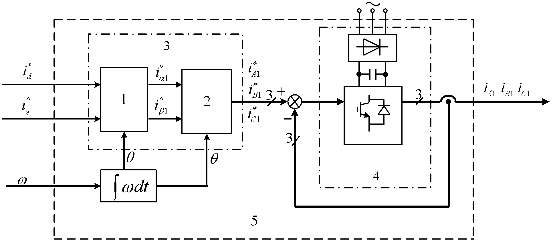
[0054] Combine Figure 4 , A bearingless permanent magnet synchronous motor suspension force feedforward compensation decoupling method of the present invention includes the following steps:

[0055] 1) Construct an extended current hysteresis PWM inverter 5, which uses the two components of the stator current of the controlled motor torque winding with The speed detection value ω is used as the input signal, and the three-phase actual current i is output A1 , I B1 , I C1 The three-phase torque winding to the controlled motor is used to adjust the speed. Such as figure 1 As shown, the extended current hysteresis PWM inverter includes coordinate transformation part 3, integral operation and current hysteresis PWM inverter 4; two components of the stator current of the controll...


PUM


Abstract

The invention discloses a suspension force feedforward compensation decoupling method and a control device of a bearingless permanent magnet synchronous motor. During control, it includes an expanded current hysteresis PWM inverter configured to supply power to the torque winding of the motor; the structure is expanded The coupled levitation force model; construct an extended feedforward compensation decoupling controller; the extended feedforward compensation decoupling controller takes two levitation force components, torque current components, permanent magnet equivalent excitation current and rotational speed as its input , the reference value of the three-phase current of the suspension winding is output, and the actual three-phase current is output after the first current hysteresis PWM inverter, which is used as the input of the extended coupling suspension force model, and the extended coupling suspension force model outputs the rotor displacement; finally, the two A decoupled suspension force subsystem and speed subsystem design a closed-loop regulator. By using the invention to control the bearingless permanent magnet synchronous motor, the stable suspension of the controlled motor can be realized, and the system has fast response, simple algorithm and excellent performance.

Description

Technical field [0001] The invention relates to the technical field of power transmission control, in particular to a sine wave surface type bearingless permanent magnet synchronous motor suspension force feedforward compensation decoupling method and control device, which is suitable for high-performance suspension operation of the surface type bearingless permanent magnet synchronous motor With frequency conversion speed control. Background technique [0002] The bearingless permanent magnet synchronous motor uses the structural similarity between the magnetic bearing and the ordinary permanent magnet synchronous motor, and superimposes the levitation winding used to generate the radial suspension force and the inherent torque winding of the ordinary permanent magnet synchronous motor on the stator. In order to achieve stable suspension of the rotor and electromagnetic torque output. Owing to the omission of mechanical bearings to support the rotor, it has a series of outstand...

Claims


Application Information

Patent Timeline
IPC IPC(8): H02P21/14H02P21/00
Inventor 张汉年孙刚徐开军
Owner NANJING COLLEGE OF INFORMATION TECH
Why Eureka
Try Eureka