Magnetic compression anastomosis ball

A magnetic and magnetic technology, applied in the field of magnetic compression anastomotic balls

Active Publication Date: 2012-07-11
徐忠法
View PDF7 Cites 3 Cited by
  • Summary
  • Abstract
  • Description
  • Claims
  • Application Information

AI Technical Summary

Problems solved by technology

However, unlike BAR, the AKA-2 ring is not resorbable and tends to break down 4 to 6 days after anastomosis
In addition, it is only used in transanal anastomosis
The limitations of BAR anastomosis include: ①failure of purse string suture; ②inaccurate estimation of colon lumen diameter; ③mucosa dehiscence; ④anastomosis failure (gut is likely to be damaged by extraintestinal extrusion); Destruction of equipment; ⑥ Delayed ring degradation; ⑦ Postoperative tenesmus and increased stool frequency may be caused by degradation products before they are discharged; ⑧ The device is large and difficult to operate; ⑨ The inner diameter of the ring is too small to cause defecation obstruction
[0016]These convincing results suggest that this device could be a revolutionary invention in colorectal practice; have doubts
Placing an anastomotic ring on the pelvic floor causes persistent anal canal sensitivity (urgency)
[0017] (5) Magnetic control anastomosis technology In the 1980s, someone invented a magnetic ring for intestinal anastomosis, but this concept has not been improved Promotion
Does not cause bowel stenosis, magnetic bowel anastomosis is innovative and has broad application prospects, but there is no previous report

Method used


Image

  • Magnetic compression anastomosis ball
  • Magnetic compression anastomosis ball
  • Magnetic compression anastomosis ball

Examples


Embodiment Construction

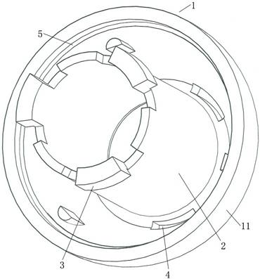
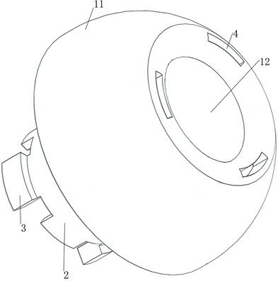
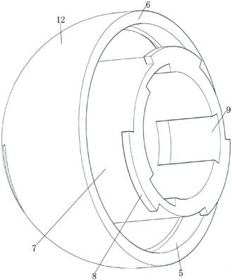
[0048] The magnetic pressure anastomotic ball as a whole includes component I and component II, Figure 1~2 shows the overall structure of assembly I, Figure 3-7 The overall structure of component II is shown, and the anastomotic ball will be introduced in detail below.

[0049] It can be seen from the figure that the assembly I includes a rotary housing I11 and a cylinder I2. In order to make the anastomotic ball less likely to damage the gastrointestinal mucosa, less likely to damage the intestinal tract when moving in the intestine after falling off, and to facilitate excretion from the body, the rotary housing I is required to have a smooth surface. The prime line of the revolving shell I is a smooth curve, and the two ends of the curve are at a certain distance from the axis. In this way, the revolving shell I has two open ends, which are respectively a large opening end and a small opening end. The distance from the point on the prime line near the large mouth end to ...


PUM


Abstract

The invention provides a magnetic compression anastomosis ball, which can assuredly avoid anastomotic leakage caused by incomplete anastomosis and comprises a rotating shell I and a rotating shell II. The rotating shell I and the rotating shell II are attracted with each other magnetically. A plain thread of the rotating shell I is a smooth curve, two ends of the curve are spaced from an axis by certain distances, so that a large opening end and a small opening end of the rotating shell I are formed, a barrel I extending axially is arranged in an inner cavity of the rotating shell I, and the inner end of the barrel I is combined with the small opening end of the rotating shell I; a plane thread of the rotating shell II is a smooth curve, two ends of the curve are spaced from an axis by certain distances, so that a large opening end and a small opening end of the rotating shell II are formed, a barrel II extending axially is arranged in an inner cavity of the rotating shell II, and the inner end of the barrel II is combined with the small opening end of the rotating shell II; and during anastomosis, the barrel I axially slides into the barrel II, and under effects of magnetic attraction force, the large opening end of the rotating shell I and the large opening end of the rotating shell II are oppositely combined so that a broken end of an anastomosis part between the large opening end of the rotating shell I and the large opening end of the rotating shell II is clamped tightly.

Description

technical field [0001] The invention relates to the field of gastrointestinal anastomosis and intestinal anastomosis, in particular to a magnetic compression anastomosis ball applied to end-to-end, end-to-side or side-to-side anastomosis of the gastrointestinal tract and end-to-end, end-to-side or side-to-side anastomosis of the intestine. Background technique [0002] Gastrointestinal anastomosis has a history of more than 100 years, and a large number of different materials have been used in gastrointestinal anastomosis, including silk thread, catgut, stainless steel suture, new monofilament thread and absorbable thread. Stapler devices have become popular among surgeons over the past 30 years. However, how to choose between manual anastomosis and instrumental anastomosis is still a matter of debate among many schools of thought. [0003] With the development of anastomotic techniques, surgical complications have gradually decreased, but anastomotic leakage is still one...

Claims


Application Information

Patent Timeline
Patent Type & Authority Applications(China)
IPC IPC(8): A61B17/11
Inventor 徐忠法
Owner 徐忠法
Why Eureka
Try Eureka