Gantry-type automatic spot welding system for battery pack

An automatic spot welding and gantry technology, applied in resistance welding equipment, welding equipment, metal processing equipment, etc., can solve the problems of high welding labor intensity, unreliable welding, enterprise loss, etc., to improve the efficiency and quality of spot welding, Reduce the labor intensity of workers, increase the number of installations and the effect of

Active Publication Date: 2012-07-11
FUJIAN NEBULA ELECTRONICS CO LTD
6 Cites 48 Cited by

AI-Extracted Technical Summary

Problems solved by technology

There are many defects in this method, which are mainly manifested in: 1. The welding labor intensity is high and the welding efficiency is low, and it is easy to cause worker fatigue
2. The utilization rate of special spot welding power supply (expensive) is extremely low, which leads to a great increase in the cost of the enterprise
3. Welding is unreliable and easy to weld, resulting in a high scrap rate and poor reliability of the battery pack, causing huge losses to the enterprise
4. The welding appearance is not good, and the solder joints are prone to burrs, yellowing, blackening and other phenomena
5. The welding time is uncontrollable...

Method used

See Fig. 2, wherein said system also comprises a base plate 3, and described base plate 3 is fixed under described column 12 and is positioned at described spot welding fixture platform 21 bottoms; Described base plate 3 upper surface is provided with With a group of slide rails 31 that utilize the described spot welding fixture platform 21 to slide, the set of slide rails 31 are arranged side by side; the described spot welding fixture platform 21 is slidably embedded on the described slide rail 31; The welding tool table 21 can slide on the base plate 3, which has high flexibility.
[0032] The present invention has a two-axis (X, Y axis) motion mechanism, and the beam can also be adjusted in height on the column to complete the adjustment of the Z axis. The invention has the following advantages: 1. It has three-axis motion capability, flexible and accurate automatic spot welding, and high production efficiency. 2. The height of the Z axis can be adjusted in a wide range, which greatly improves the adaptability of the welding machine to batteries of different heights. 3. A large number of batteries are clamped at one time. 4. The equipment modular combination design of the system can adapt to horizontal and hori...

Abstract

The invention provides a gantry-type automatic spot welding system for a battery pack, which comprises a spot welding device and a spot welding jig fixing device which are vertically arranged and are connected with a PLC (programmable logic controller) of the system. The spot welding device comprises a beam, a group of opposite vertical columns in parallel, a spot welding mechanism, an X-axis sliding table, a Y-axis movement mechanism and an X-axis movement mechanism, wherein the vertical columns are used for adjusting the height of the beam, the X-axis sliding table is used for fixing the spot welding mechanism, the Y-axis movement mechanism enables the spot welding mechanism to transversely move, and the X-axis movement mechanism enables the X-axis sliding table to transversely move. The spot welding jig fixing device comprises a spot welding jig platen and a clamping mechanism for clamping a spot welding jig, wherein the clamping mechanism is arranged on the spot welding jig platen and is perpendicular to the spot welding mechanism. By the aid of a gantry-type structure, clamping is performed once, cells are numerous, spot welding parameters are controllable, and the system is fast in running speed, high in spot welding efficiency, highly adaptable to the cells, accurate in positioning and fine in spot welding quality.

Application Domain

Technology Topic

Image

  • Gantry-type automatic spot welding system for battery pack
  • Gantry-type automatic spot welding system for battery pack
  • Gantry-type automatic spot welding system for battery pack

Examples

  • Experimental program(1)

Example Embodiment

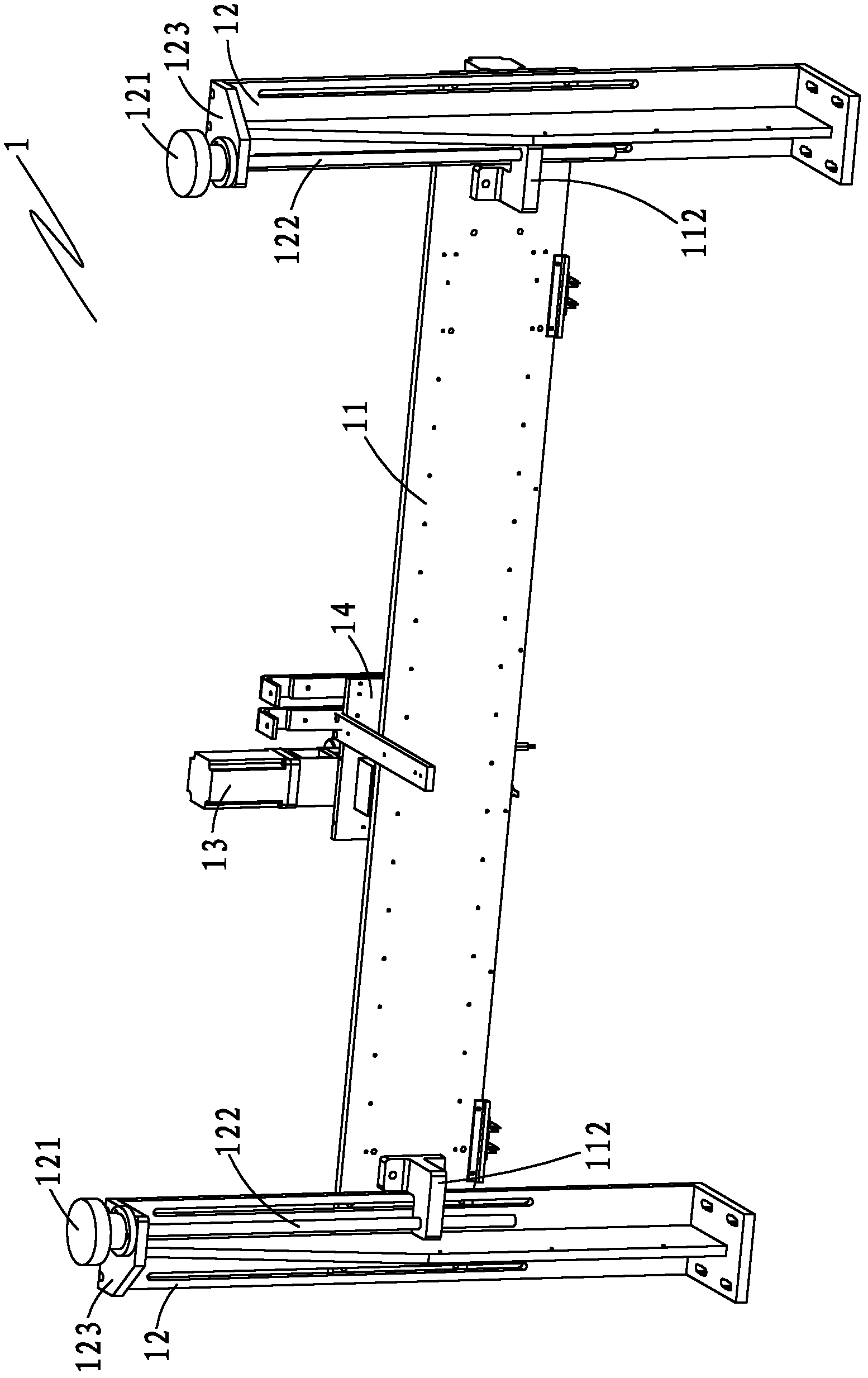
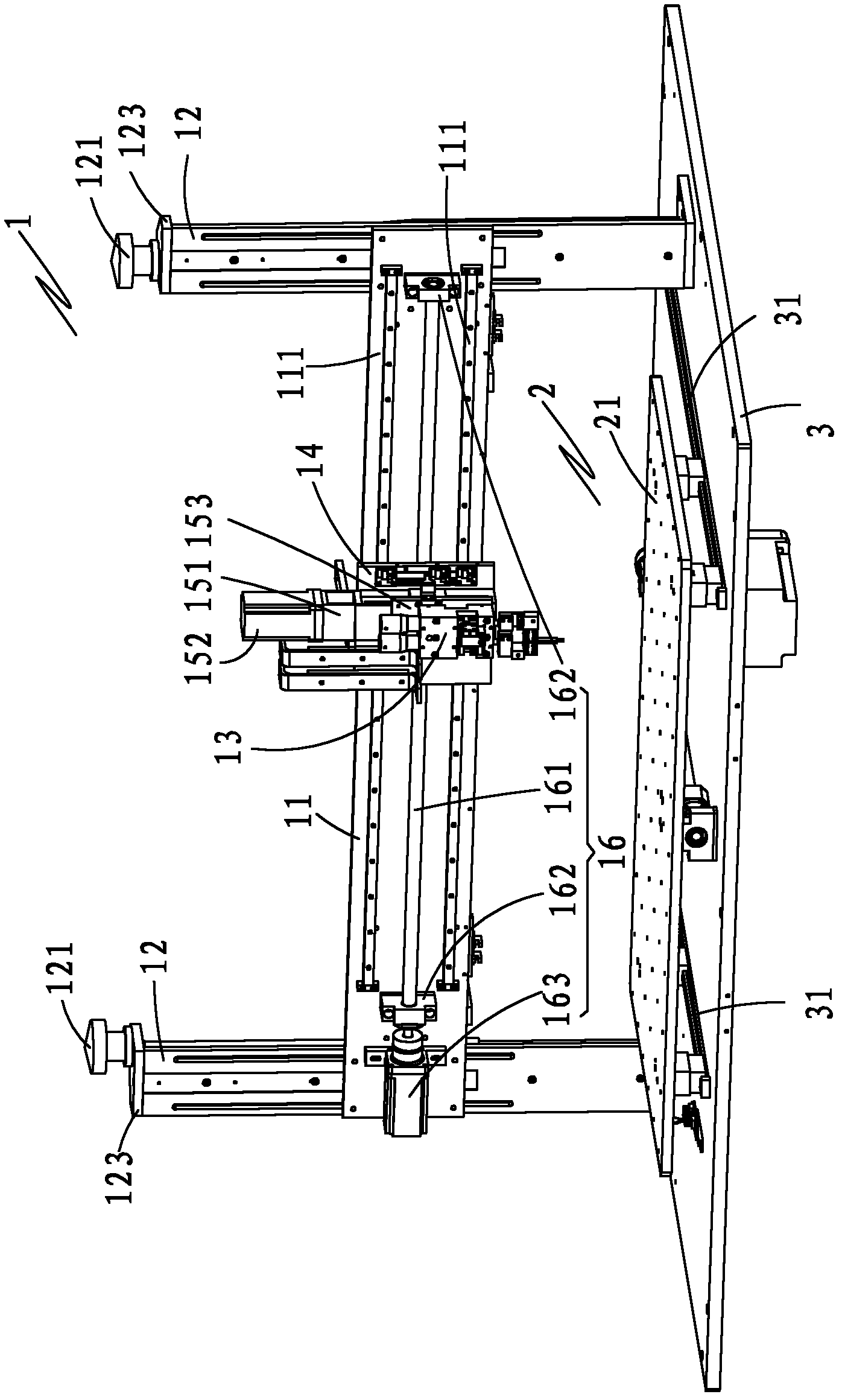
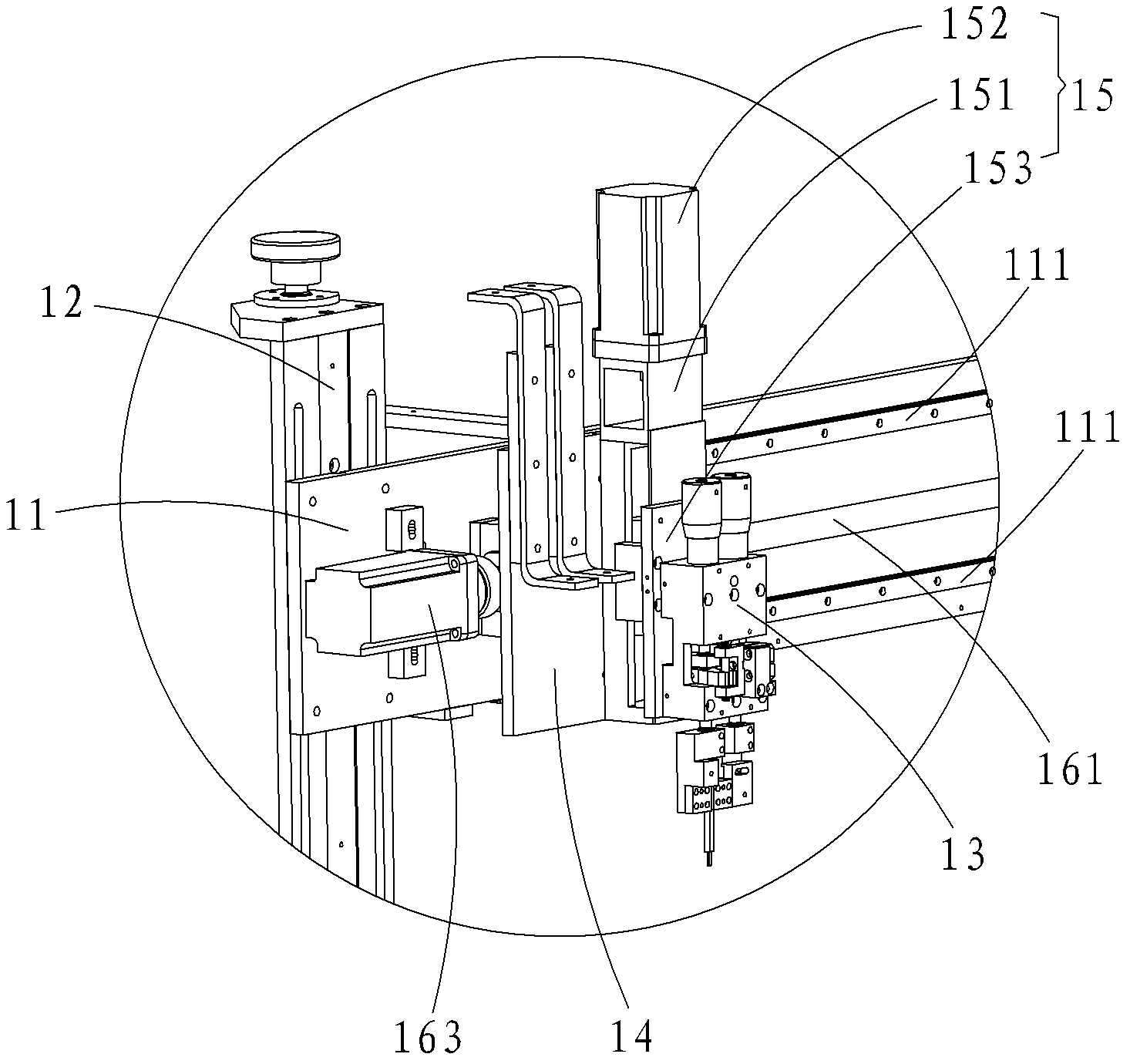
[0021] see figure 1 and figure 2 As shown, a gantry-type automatic spot welding system of a battery pack of the present invention includes a spot welding device 1 and a spot welding fixture fixing device 2 ( figure 1 The spot welding fixture fixing device is not shown); the spot welding device 1 includes a beam 11, a set of upright columns 12 arranged side by side opposite to adjust the height of the beam 11, a spot welding mechanism 13, and a spot welding mechanism 13 for fixing the point The X-axis slide table 14 of the welding mechanism 13, the Y-axis motion mechanism 15 for laterally moving the spot welding mechanism 13, and the X-axis motion mechanism 16 for laterally moving the X-axis slide table 14; the bottom of the beam 11 is arranged in parallel There are two guide rails 111, the surface of the beam 11 is provided with a set of symmetrical beam fixing bases 112, the two beam fixing bases 112 are respectively slidably embedded on the column 12 through a screw 122 with a hand wheel 121, so as to This facilitates the movement of the beam 11 on the column 12; the rotation of the handwheel 121 drives the longitudinal movement of the screw 122, thereby driving the beam 11 to move on the column 12; the end of the column 12 is provided with a screw fixing seat 123 for fixing the screw 122; The X-axis sliding table 14 is vertically arranged on the bottom of the beam 11 and nested on the two guide rails 111 ; the Y-axis motion mechanism 15 is arranged on the X-axis sliding table 14 , and the spot welding mechanism 13 It is fixedly arranged on the Y-axis movement mechanism 15 and is perpendicular to the spot welding tool fixing device 2; the X-axis movement mechanism 16 for laterally moving the X-axis slide table 14 is arranged at the bottom of the beam 11 and located at the bottom of the beam 11. between the two guide rails 111 .
[0022] like image 3As shown, the Y-axis motion mechanism 15 includes a module slide 151 and a Y-axis servo motor 152 for controlling the lateral movement of the module slide 151; The fixing plate 153 of the welding mechanism 13; the module sliding table 151 is vertically arranged on the X-axis sliding table 14, the fixing plate 153 is fixed on the module sliding table 151, and the Y-axis servo motor 152 It is arranged at the end of the module slide 151 to control the longitudinal movement of the module slide 151 . See figure 2 , the X-axis motion mechanism 16 includes a cross-beam screw 161, a set of bearing seats 162 for fixing the cross-beam screw 161 and a set of bearing seats 162 for controlling the X-axis sliding table 14 to slide on the two guide rails 111. The X-axis servo motor 163; the bearing seat 162 is fixed on the bottom of the beam 11 and located between the two guide rails 111, the beam screw 161 is fixed between the two bearing seats 162 and is connected with the beam 11 parallel; the bottom of the X-axis slide 14 is also sleeved on the beam screw 161; the X-axis servo motor 163 is fixed on the bottom of the beam 11 and connected with the beam screw 161, so that the X-axis servo motor The motor 163 drives the X-axis slide table 14 to move while controlling the movement of the beam screw 161 .
[0023] like Figure 4 As shown, the spot welding tool fixing device 2 includes a spot welding tool platen 21 and a clamping mechanism 23 for clamping the spot welding tool 4, and the clamping mechanism 23 is arranged on the spot welding tool platen 21. and perpendicular to the spot welding mechanism 13 .
[0024] The clamping mechanism 23 includes a set of spot welding tool guide positioning plates 231 and spot welding tool limit blocks 232 arranged side by side opposite to each other; the spot welding tool guide positioning plate 231 is fixed on the spot welding tool platen 21, The spot welding tool guide positioning plate 231 is provided with a pressing plate 233 with a pressing hand wheel 2331, the pressing hand wheel 2331 is used to adjust the pressure of the pressing plate 233; the pressing plate 233 is connected to the point The welding tool guide positioning plate 231 is vertical; the spot welding tool limit block 232 is fixed on the spot welding tool table 21 and is perpendicular to the pressing plate 233, the spot welding tool limit block 232, The two pressing plates 233 enclose a space for clamping the spot welding tool 4 .
[0025] see as figure 2 , wherein the system further includes a bottom plate 3, the bottom plate 3 is fixed under the column 12 and is located at the bottom of the spot welding tool platen 21; the upper surface of the bottom plate 3 is provided with the spot welding tool A set of slide rails 31 on which the platen 21 slides, the set of slide rails 31 are arranged side by side and opposite to each other; the spot welding tool platen 21 is slidably embedded on the slide rails 31; in this way, the spot welding tool platen 21 can be Sliding on the bottom plate 3, high flexibility.
[0026] like Figure 5 and Image 6 As shown, the spot welding mechanism 13 includes a welding pin 131, a welding pin fixing seat 132, a welding seat body 133 and a pressure regulating device 134 for adjusting the pressure of the welding pin; the welding seat body 133 is embedded with a positive electrode A guide post 135 and a negative pole guide post 136, the welding pin holder 132 is connected to the positive pole guide post 135 and the negative pole guide post 136 of the main body 133 of the solder holder; the solder pin holder 132 is embedded with the solder pin 131 ; The pressure regulating device 134 is embedded in the tail of the welding seat body 133 and is connected with the positive pole guide post 135 and the negative pole guide post 136 .
[0027] On the welding seat body 133, a metallurgical cylinder 137 and a rotating device 138 for rotating the positive pole guide column 135 are arranged side by side opposite to each other. The rotating device 138 includes a swing arm 1381 and a push rod 1382; One end is nested on the positive guide column 135, and the other end is fixedly connected to the push rod 1382; the push rod 1382 is connected to the cylinder shaft (not shown) of the smelting cylinder 137; in this way, the spot welding mechanism 13 The jig cylinder 137 in the middle works on the push rod 1382 of the rotating device 138 to make the swing arm 1381 rotate so as to rotate the positive pole guide column 135, which eliminates the phenomenon that the welding needle 131 sticks to the needle.
[0028] The pressure regulating device 134 includes a set of pressure regulating knobs 1341, a set of transition sleeves 1342, a set of screw rods 1343, a set of springs 1344, a set of upper spring support platforms 1345 and a set of lower spring support platforms 1346; the set of The under-spring support platform 1346 is respectively sleeved on the positive electrode guide column 135 and the negative electrode guide column 136; the set of pressure regulating knobs 1341 are respectively sleeved on the transition sleeve 1342 and fixed by the screw rod 1343; the screw rod The tail of 1343 is sleeved with the spring upper support platform 1345; the spring 1344 is nested between the upper support platform 1345 and the lower support platform 1346, and the upper support platform 1345 and the lower support platform 1346 correspond; When the knob 1341 rotates, the screw 1343 rotates together, thereby compressing the spring 1344, and the positive pole 135 and the negative pole 136 connected to the other end of the spring 1344 can slide to adjust the pressure of the welding needle 131.
[0029] like Figure 7 As shown, the spot welding tool 4 of the present invention includes an upper template 41 with an upper locking portion 411 on both sides, a lower template 42 with a lower locking portion 421 on both sides, and a set of locking screws. 431 of the locking handwheel 43; the upper locking part 411 of the upper template 41 and the lower locking part 421 of the lower template 42 are locked by the locking handwheel 43 with the locking screw 431, so The surfaces of the upper template 41 and the lower template 42 are provided with a plurality of spot welding windows 44 . The spot welding tools can also be other types of spot welding tools.
[0030] The working principle of the present invention is as follows:
[0031] Before the spot welding system starts to work, the pressure of the welding pin 131 is adjusted by the pressure adjustment device 134, and then the height of the beam 11 is adjusted to suit the height of the spot welding cell. By setting the column 12 for adjusting the height of the beam to adjust the height of the beam 11; when the handwheel 121 on the column 12 is rotated, the screw rod 122 rotates the beam fixing seat 112 to rise or fall with the rotation of the screw rod 122, thereby adjusting the height of the beam 11, after the height adjustment of the beam 11 is completed , pack the battery into the spot welding fixture 4, the spot welding fixture 4 is divided into an upper template 41 and a lower template 42, the upper template 41 and the lower template 42 fix the battery pack, and the locking handwheel 43 with the locking screw 431 is used. The upper template 41 and the lower template 42 are locked and closed, and the two templates are clamped, thereby fixing the battery pack. After the battery is packed into the spot welding jig 4, the spot welding jig 4 is limited by the spot welding tool guiding positioning plate 231 and the spot welding tool limit block 232, and the pressing handwheel 2331 is rotated to push the pressing plate 233 forward. , press the spot welding tool 4. After the spot welding tool 4 is fixed, press the start button of the system, and the corresponding spot welding position data is stored in the microcomputer. After pressing the start, the microcomputer sends the data to the PLC. After the PLC obtains the position data, the X-axis servo motor 163 controls the X-axis slide. The positioning of the stage 14 in the beam 11 is to complete the position of the spot welding mechanism 13 in the beam 11; then the positioning of the spot welding mechanism 13 in the Y axis is controlled by the Y axis servo motor 152; after the X/Y axis positioning is completed, Start the spot welding operation. When the welding needle 131 in the spot welding device 1 contacts the nickel sheet of the battery, the PLC of the system controls the spot welding power source to discharge, and at the same time, the tool cylinder 147 in the spot welding device 1 performs work on the rotating device 148 to make the positive pole guide column. 145 rotation, to break the phenomenon that the solder pin sticks to the pin. After one spot welding is completed, continue to the next spot welding until all the welding spots are completed. After all the welding points on one side of the spot welding fixture 4 are completed, loosen the fixture, turn the entire spot welding fixture 4 over and clamp it on one side, and spot weld the other side. After both sides are completed, release the fixture and take out the battery pack to complete a process.
[0032] The present invention has a two-axis (X, Y-axis) motion mechanism, and the height of the beam can also be adjusted on the upright column to complete the adjustment of the Z-axis. The invention has the following advantages: 1. It has three-axis motion capability, automatic spot welding is flexible and accurate, and the production efficiency is high. 2. The height of Z-axis can be adjusted in a wide range, which greatly improves the adaptability of the welding machine to cells of different heights. 3. A large number of cells can be clamped at one time. 4. The modular design of the system equipment can adapt to horizontal and horizontal spot welding machines at the same time, and the pressure and spacing are adjustable, and the positive electrode welding needle can be rotated. The spot welding tool 4 of the present invention cooperates with PLC precise control to ensure the rapid movement and precise positioning of the welding needle. The welding needle is equipped with a precision spring and a pressure adjustment device to ensure consistent spot welding pressure. At the same time, the welding needle assembly tool cylinder rotates after the welding is completed to solve the problem of sticking needles. The system PLC scans the input voltage at high speed for a long time. When the power supply fluctuates, the compensation data will be calculated immediately, and the welding energy will be changed, so that the welding will not cause false welding or explosion due to voltage fluctuation. Continue welding. Pre-welding removes the oxide layer, eliminates debris, and reduces sparks; continuous welding ensures that the solder joints are beautiful and firm, the solder joint size is uniform without burrs, and the welding effect is consistent every time, ensuring the welding quality and appearance.
[0033] The above descriptions are only preferred embodiments of the present invention, and all equivalent changes and modifications made according to the scope of the patent application of the present invention shall fall within the scope of the present invention.

PUM

no PUM

Description & Claims & Application Information

We can also present the details of the Description, Claims and Application information to help users get a comprehensive understanding of the technical details of the patent, such as background art, summary of invention, brief description of drawings, description of embodiments, and other original content. On the other hand, users can also determine the specific scope of protection of the technology through the list of claims; as well as understand the changes in the life cycle of the technology with the presentation of the patent timeline. Login to view more.

Similar technology patents

Rapid construction process for sinking vertical shaft pit shaft with large diameter on deep surface soil layer by utilizing freezing method

InactiveCN101694160ASave on rental costsReduce manual labor intensityShaft sinkingShaft liningBedding supportHigh strength concrete
Owner:中煤第一建设有限公司第四十九工程处

Classification and recommendation of technical efficacy words

Why Eureka
Try Eureka