Rotational angle detection device

A technology of rotation angle detection and rotation angle, which is applied in measuring devices, electromechanical devices, and electrical devices, etc., can solve the problems of cost increase and achieve the effect of reducing costs and simplifying the circuit structure

Inactive Publication Date: 2012-07-11
OMRON AUTOMOTIVE ELECTRONICS CO LTD
View PDF6 Cites 14 Cited by
  • Summary
  • Abstract
  • Description
  • Claims
  • Application Information

AI Technical Summary

Problems solved by technology

[0016] In the above-mentioned dual-excitation rotation angle detection device 200, two circuits of the excitation signal generation circuit 53 and the reverse excitation signal generation circuit 54 are required in the excitation circuit 52, so there is a problem of increased cost.
In addition, the above-mentioned Patent Document 2 describes that two salient poles among excitation double salient poles wound with coils in a differential manner are excited by signals with different phases from each other, and based on the combination of outputs from the midpoints of the respective coils, A resolver that detects the rotation angle using a signal, but even in this method, multiple signal sources for generating signals with different phases are required

Method used


Image

  • Rotational angle detection device
  • Rotational angle detection device
  • Rotational angle detection device

Examples


Embodiment Construction

[0055] Hereinafter, embodiments of the present invention will be described with reference to the drawings. The same reference numerals are attached to the same parts or corresponding parts in the respective drawings.

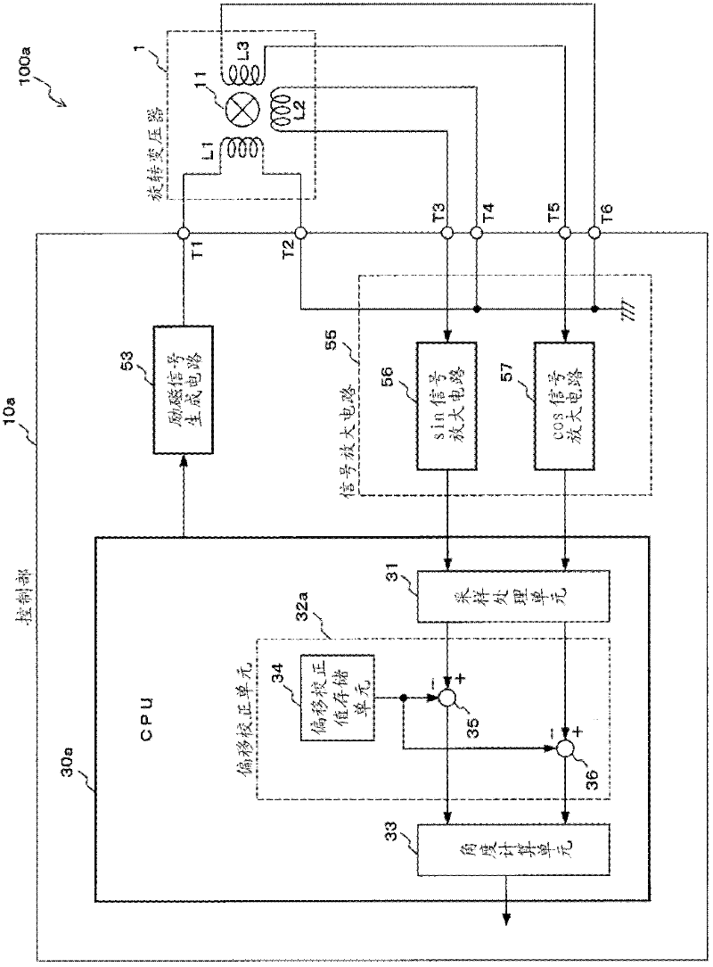
[0056] figure 1 It is a block diagram of the rotation angle detection device of 1st Embodiment of this invention. The rotation angle detection device 100a is composed of a resolver 1 and a control unit 10a. Regarding resolver 1, with the Figure 6 as well as Figure 7 The same as described in , so the description is omitted here, and the details of the control unit 10a will be described below.

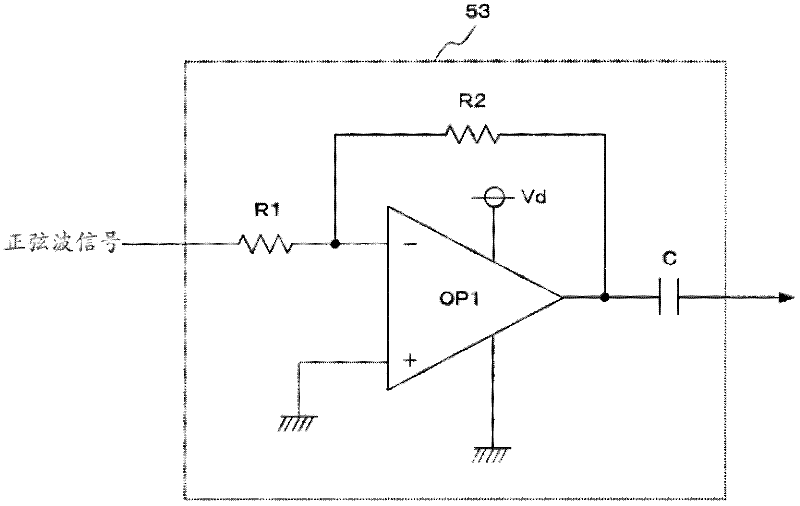
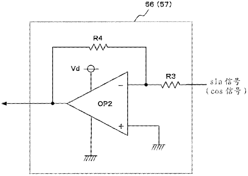
[0057] The control unit 10a includes an excitation signal generation circuit 53, a signal amplification circuit 55, and a CPU 30a. Not set in control unit 10a Figure 9 Inverted excitation signal generation circuit 54, and only excitation signal generation circuit 53 is provided. That is, this rotation angle detection device 100 a is a single excitation type rotat...


PUM


Abstract

The present invention provides a rotational angle detection device that reduces cost thereof by simplifying an excitation circuit and is capable of detecting an angle accurately even in the case where offsets occur in output signals. The rotational angle detection device (100a) has a resolver (1) in which an excitation coil (L1) and a output coil (L2, L3) are provided , an excitation signal generator circuit (53) that generates an excitation signal and sends the excitation signal to the excitation coil (L1), and CPU (30a) which detects the amplitudes of the output signals of the output coils (L2, L3) in a predetermined cycle and calculates the rotational value with the value detected. CPU (30a) comprises an offset correction value storage unit (34) that stores offset correction value for correcting the offsets of the two sampling signals obtained from the respective output signal of the output coil (L2, L3). An angle calcualtion unit (33) calculates the rotational angle based on the respective sampling unit with offsets removed.

Description

technical field [0001] The present invention relates to a device for detecting the rotation angle of a motor or the like using a resolver, and more particularly to a single excitation system rotation angle detection device using a single excitation circuit. Background technique [0002] A resolver is a rotation angle sensor that includes an exciting coil and two output coils around a rotor connected to a shaft. In the rotation angle sensor, there is also a rotary encoder (rotary encoder) in addition to the resolver, but since the rotary encoder uses an optical element or a magnetoresistive element, it is easily affected by temperature, noise, dust, etc., and the environmental resistance (environmental resistance) resistance) is poor. On the other hand, a resolver is basically only composed of a coil and an iron core, and does not use the above-mentioned components, so it can be used under severe environmental conditions. For example, it is used to detect the rotation angle ...

Claims


Application Information

Patent Timeline
Patent Type & Authority Applications(China)
IPC IPC(8): G01B7/30
CPCH02K29/08H02K24/00G01D5/2046
Inventor 薮口教定多田刚
Owner OMRON AUTOMOTIVE ELECTRONICS CO LTD
Why Eureka
Try Eureka