Automatic testing device and testing method for laser damage threshold value

An automatic test device and laser damage threshold technology, applied in the direction of testing optical performance, etc., can solve the problems of a test device without a multi-purpose general-purpose commercial laser threshold, a large uncertainty in test data, and uneven indicators. The effect of high degree of automation, guaranteed reliability and strong applicability

Inactive Publication Date: 2012-07-11
BEIJING GK LASER TECH
View PDF5 Cites 18 Cited by
  • Summary
  • Abstract
  • Description
  • Claims
  • Application Information

AI Technical Summary

Problems solved by technology

[0004] However, due to the diversity of laser wavelengths, energies, and pulse widths, there is no multi-purpose general-purpose commercial laser threshold testing device on the market so far.
Everyone is based on the actual needs of their own

Method used


Image

  • Automatic testing device and testing method for laser damage threshold value
  • Automatic testing device and testing method for laser damage threshold value

Examples


Embodiment Construction

[0035] The technical solutions of the present invention will be further specifically described below through specific embodiments and in conjunction with the accompanying drawings.

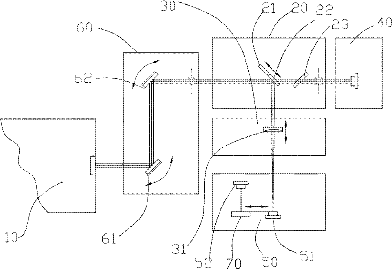
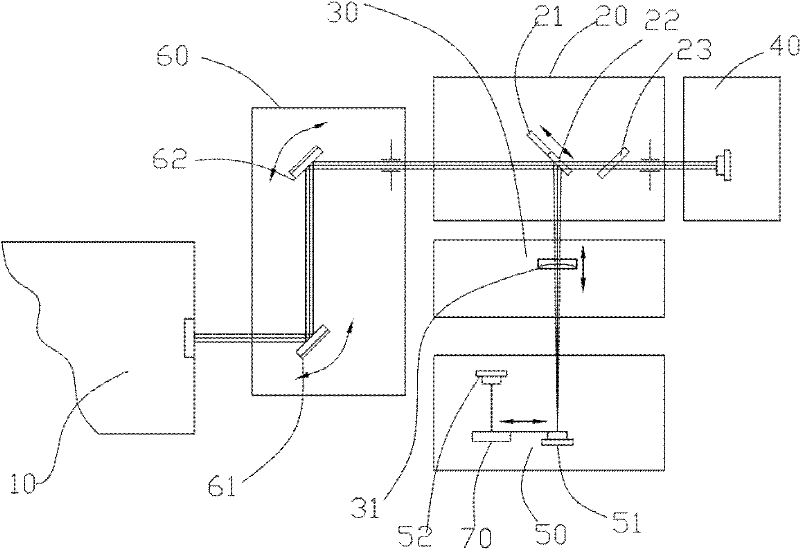
[0036] Please refer to figure 1 As shown, a laser damage threshold automatic testing device 100 includes: a laser 10, a spectroscopic attenuation system 20, a focusing system 30, an energy collection system 40, a sample stage, a beam collection system 50 and a processing system (not shown), wherein , the spectroscopic attenuation system 20 and the energy collection system 40 are located on the first main optical axis of the laser beam emitted by the laser 10, the focusing system 30 and the beam collection system 50 are located on the second main optical axis perpendicular to the first main optical axis On the two main optical axes, the spectral attenuation system 20 includes a high reflection mirror 21, a high transmission mirror 22, a linkage mechanism, a figure-eight compensation high transmissi...


PUM


Abstract

The invention discloses an automatic testing device and an automatic testing method for a laser damage threshold value. The automatic testing device comprises a laser, a light splitting attenuation system, a focusing system, an energy acquisition system, a beam acquisition system and a processing system, wherein the light splitting attenuation system comprises a high reflective mirror, a high transmitting mirror, a linkage mechanism and a splay compensation high transmitting mirror; and the high reflective mirror and the high transmitting mirror are transposed under the action of the linkage mechanism, and in the transposition process, the front mirror surfaces of the high reflective mirror and the high transmitting mirror are positioned on the same plane. The testing method comprises the following steps of: a) calculating damage energy on the unit area of a laser beam; b) dotting a lens to be tested to form a plurality of test dots by using the laser beam, and observing the damage condition of the surface of the lens to be tested by using the beam acquisition system; and c) regulating the energy of the laser beam, and repeating the steps a and b until the damage threshold value is measured. The structure and the testing method provided by the invention are low in test errors and high in applicability and accuracy.

Description

technical field [0001] The invention relates to a technology for testing the laser damage threshold of lenses (including coating layers) used in a laser light path, in particular to an automatic laser damage threshold test device and a test method. Background technique [0002] In high-power and high-energy laser systems, there are a large number of thin-film components, and the ability of these components to resist laser damage is closely related to the normal and effective operation of the system. Existing studies have shown that the damage of thin film components under strong laser is completely determined by the anti-laser ability of the component surface. Therefore, with the continuous expansion of the application range of high-power lasers, the importance of thin film resistance to laser damage has become increasingly prominent, so that the laser damage threshold has become an indispensable performance index for optical thin film components. The thin film must have a ...

Claims


Application Information

Patent Timeline
IPC IPC(8): G01M11/02
Inventor 樊仲维王家赞
Owner BEIJING GK LASER TECH
Why Eureka
Try Eureka