Flash memory development system

A flash memory and memory controller technology, applied in static memory, instruments, etc., can solve problems such as unsatisfactory solutions, and achieve the effect of improving cost competitiveness

Active Publication Date: 2012-07-11
ASOLID TECH
View PDF3 Cites 2 Cited by
  • Summary
  • Abstract
  • Description
  • Claims
  • Application Information

AI Technical Summary

Problems solved by technology

However, there is no satisfactory answer in terms of both cost and efficacy

Method used


Image

  • Flash memory development system
  • Flash memory development system
  • Flash memory development system

Examples


Embodiment Construction

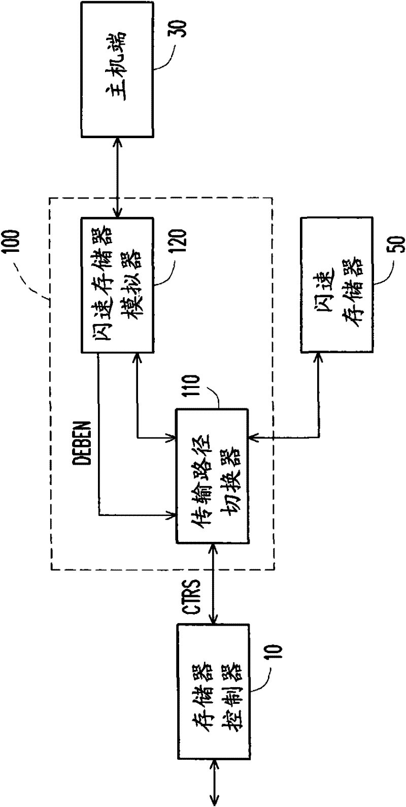
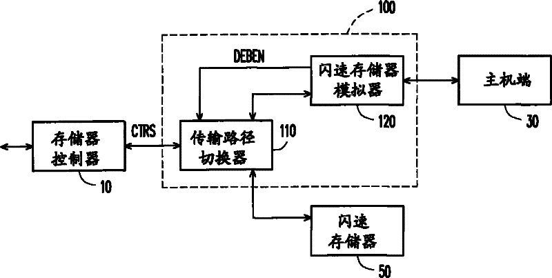
[0032] First please refer to figure 1 , figure 1 A schematic diagram of a flash memory module development system 100 according to an embodiment of the present invention is shown. Wherein, the development system 100 includes a transmission path switcher 110 and a flash memory emulator 120 . The transmission path switcher 110 is serially connected between the memory controller 10 of the flash memory module and the signal transmission path of the flash memory 50 . The flash memory emulator 120 is coupled to the transmission path switcher 110, receives at least one control command CTRLS from the memory controller through the signal transmission path, and interprets the received control command CTRLS to generate at least one simulation in response to the control command CTRLS response data. The flash memory emulator 120 also transmits the simulated response data to the memory controller through the signal transmission path.

[0033] The above-mentioned signal transmission path ...


PUM


Abstract

A flash memory development system comprises a transmission path switching device and a flash memory simulator. The transmission path switching device is connected in series between a memory controller and a signal transmission path of the flash memory and used for receiving debug startup signals. The flash memory simulator is used for receiving at least one control command from the memory controller through the signal transmission path. The flash memory simulator is used for interpreting and responding the control command to generate at least one simulation and response data. The flash memory simulator is also used for sending simulation and response data to the memory controller through the signal transmission path. The system can enhance cost competitiveness of products without expensive apparatuses or complicated method.

Description

technical field [0001] The invention relates to a flash memory development system. Background technique [0002] Flash memory (flash memory) is a programmable (programmable) read only memory (read only memory, ROM), which allows multiple erasing and updating of stored data. [0003] When debugging the flash memory and its memory controller, a so-called development system is often used to complete it. In the known technical field, such a developed system involving a flash memory module can be constructed using a logic analyzer (Logical Analyzer, LA) or a universal asynchronous receiver / transmitter (UART). Although the above-mentioned known method of using a logic analyzer can provide relatively detailed debugging data, it is quite expensive in price. In addition, a logic analyzer cannot provide a long-term debug record, so it is not a good choice. However, in the technology using the Universal Asynchronous Receiver Transmitter, the error detection records generated by it c...

Claims


Application Information

Patent Timeline
Patent Type & Authority Applications(China)
IPC IPC(8): G11C29/42
Inventor 刘亦峻
Owner ASOLID TECH
Why Eureka
Try Eureka