Gas pipeline system of reaction chamber and control method of gas pipeline system

A technology of gas pipelines and reaction chambers, which is applied in the direction of discharge tubes, electrical components, circuits, etc., can solve the problems of impure cooling gas and easy contamination of wafers, etc., and achieve the effect of reducing the possibility

Active Publication Date: 2012-07-11
SEMICON MFG INT (SHANGHAI) CORP +1
View PDF5 Cites 4 Cited by
  • Summary
  • Abstract
  • Description
  • Claims
  • Application Information

AI Technical Summary

Problems solved by technology

In the above conversion process, since the complete closing of the butterfly valve 201 takes time, the following situations are likely to occur when the butterfly valve 201 starts to close and the cooling valve 202 just opens: the reaction chamber 100 is also similar to a vacuum state, the air pressure is extremely small, and The air pressure in the air-cooling unit of the turbo ventilation pump 102 is relatively high, and th

Method used


Image

  • Gas pipeline system of reaction chamber and control method of gas pipeline system
  • Gas pipeline system of reaction chamber and control method of gas pipeline system
  • Gas pipeline system of reaction chamber and control method of gas pipeline system

Examples


Embodiment Construction

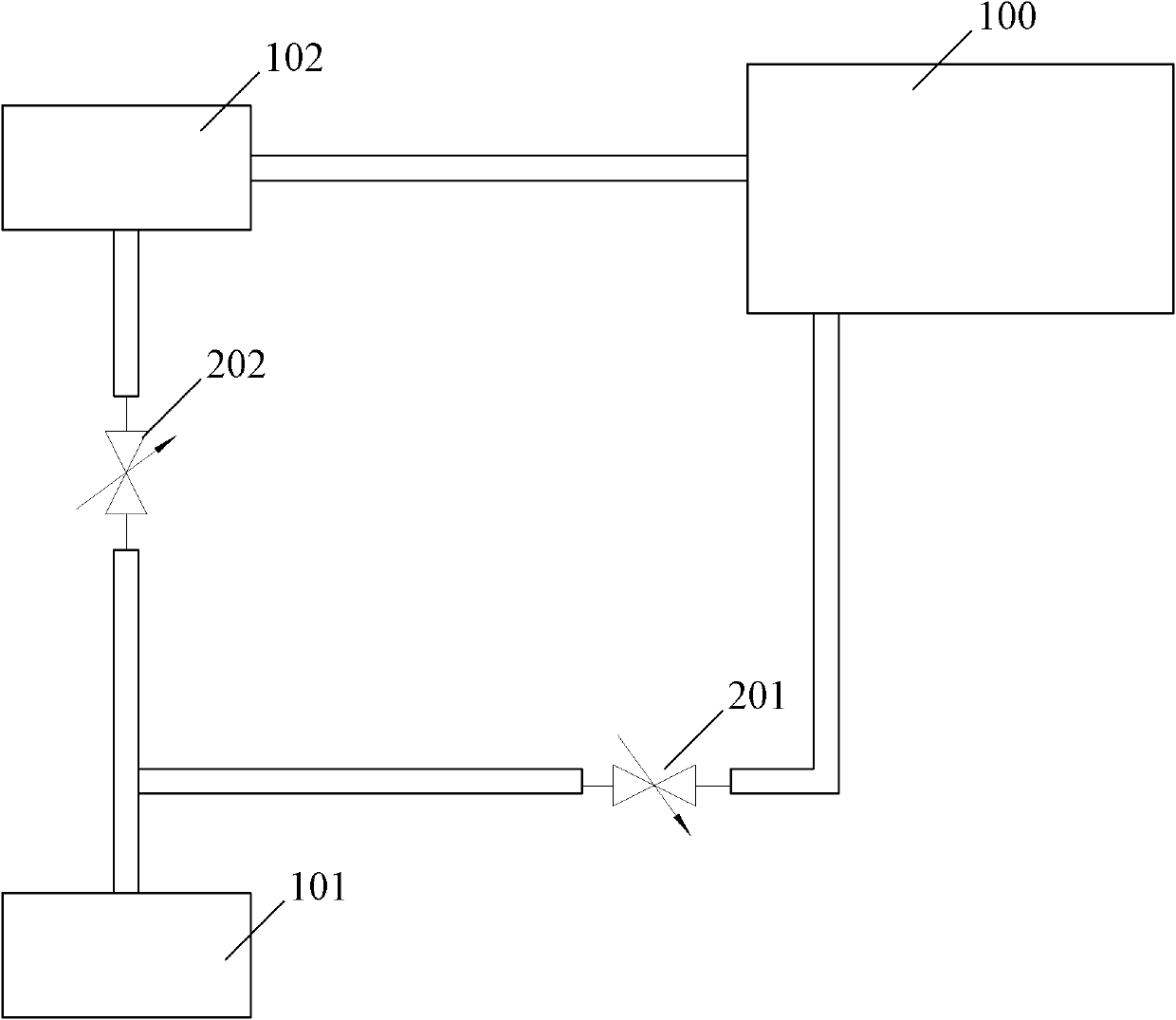
[0027] The existing reaction chamber gas pipeline system uses a rough pump to pump air from the reaction chamber and discharge the cooling gas from the turbo vent pump. When the valve is switched, due to the pressure difference between the reaction chamber and the turbo vent pump air cooling unit, it is easy to appear The cooling gas backfills into the reaction chamber and contaminates the wafer. The present invention solves the above problems by reducing the air pressure of the air cooling unit, monitoring the air pressure difference between the reaction chamber and the air cooling unit of the turbo vent pump, and controlling the opening and closing of the butterfly valve.

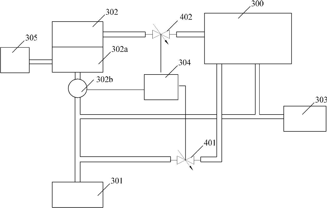
[0028] Such as figure 2 As shown, the basic structure of the gas transmission pipeline system of the present invention includes: a rough pump 301, connected to the reaction chamber 300 via a butterfly valve 401, and used to pump air to the reaction chamber 300; a turbine ventilation pump 302, the turbine...


PUM


Abstract

The invention provides a gas pipeline system of a reaction chamber and a control method of the gas pipeline system. The gas pipeline system comprises a roughing pump connected with a reaction chamber by a butterfly damper for exhausting gas in the reaction chamber; a turbine aerating pump connected with the reaction chamber for aerating the reaction chamber, wherein a gas cooling unit of the turbine aerating pump is communicated with the roughing pump; and a valve control unit for comparing the gas pressure in the gas cooling unit with gas pressure in the reaction chamber and closing a butterfly valve when the gas pressure in the gas cooling unit is more than that of the reaction chamber. In the invention, the roughing pump always exhausts gas in the gas cooling unit when working, can reduce gas pressure in the gas cooling unit and enable the gas pressure to keep balance with the gas pressure of the reaction chamber; the valve control unit compares the gas pressures, controls opening or closing of the butterfly valve, thereby effectively preventing the cooling gas from being reversely filled to the reaction chamber.

Description

technical field [0001] The invention relates to the field of semiconductor equipment, in particular to a gas delivery pipeline system of a reaction chamber and a control method thereof. Background technique [0002] In the field of semiconductor processing and production, equipment such as plasma processing devices, vapor deposition devices, and cleaning devices need to feed gas into the reaction chamber or vacuumize to form a vacuum environment during operation. The gas pipeline system connected to the above reaction chamber is usually Including exhaust pumps for exhaust, ventilation pumps for ventilation, etc. Among them, in order to simplify the pipeline, the above-mentioned exhaust pump and ventilation pump are not independently installed, but share part of the pipeline, and the airflow direction in the pipeline is controlled by a valve. For more information about the gas pipeline system in the reaction chamber of semiconductor equipment, please refer to the Chinese pat...

Claims


Application Information

Patent Timeline
IPC IPC(8): H01J37/32
Inventor 聂佳相孔祥涛何伟业陈碧钦
Owner SEMICON MFG INT (SHANGHAI) CORP
Why Eureka
Try Eureka