
Micro electronic mechanical system (MEMS) load line type 2-bit phase shifter based on left-handed transmission line

A left-handed transmission line, line-type technology, applied in waveguide-type devices, coupling of optical waveguides, components of TV systems, etc., can solve the problems of small phase shift and large number of switches in MEMS switches, and achieve fewer switches and fewer switches. The effect of using quantity and low loss

Inactive Publication Date: 2012-07-11
HARBIN INST OF TECH
View PDF3 Cites 3 Cited by
  • Summary
  • Abstract
  • Description
  • Claims
  • Application Information

AI Technical Summary

Problems solved by technology

[0004] The purpose of the present invention is to provide a MEMS load line type 2 phase shifter based on the left-hand transmission line in order to solve the problem of small MEMS switch phase shift and large number of switches in the 2-bit MEMS phase shifter

Method used


Image

  • Micro electronic mechanical system (MEMS) load line type 2-bit phase shifter based on left-handed transmission line
  • Micro electronic mechanical system (MEMS) load line type 2-bit phase shifter based on left-handed transmission line
  • Micro electronic mechanical system (MEMS) load line type 2-bit phase shifter based on left-handed transmission line

Examples


specific Embodiment approach 1

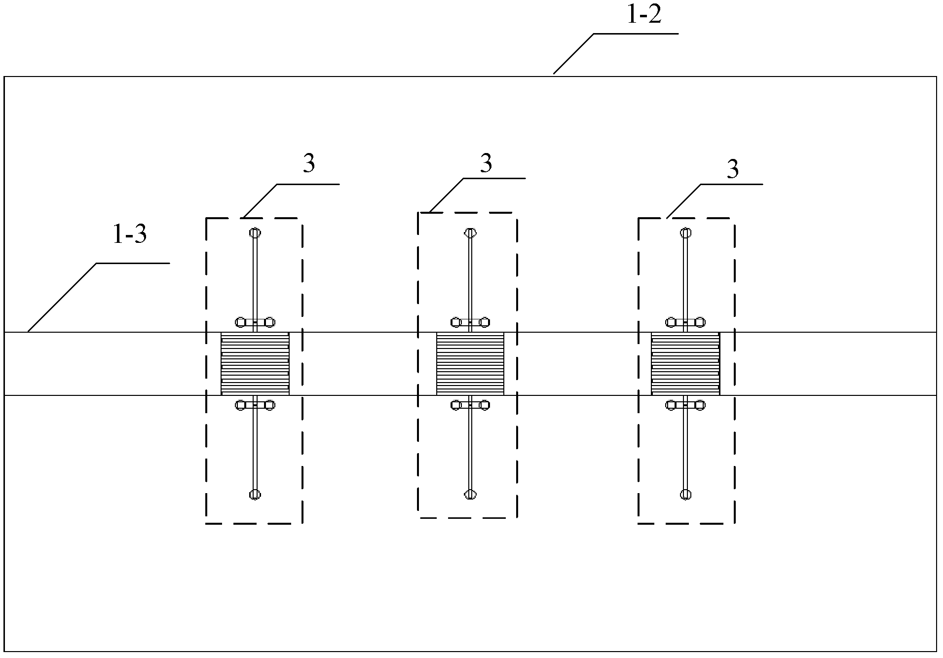
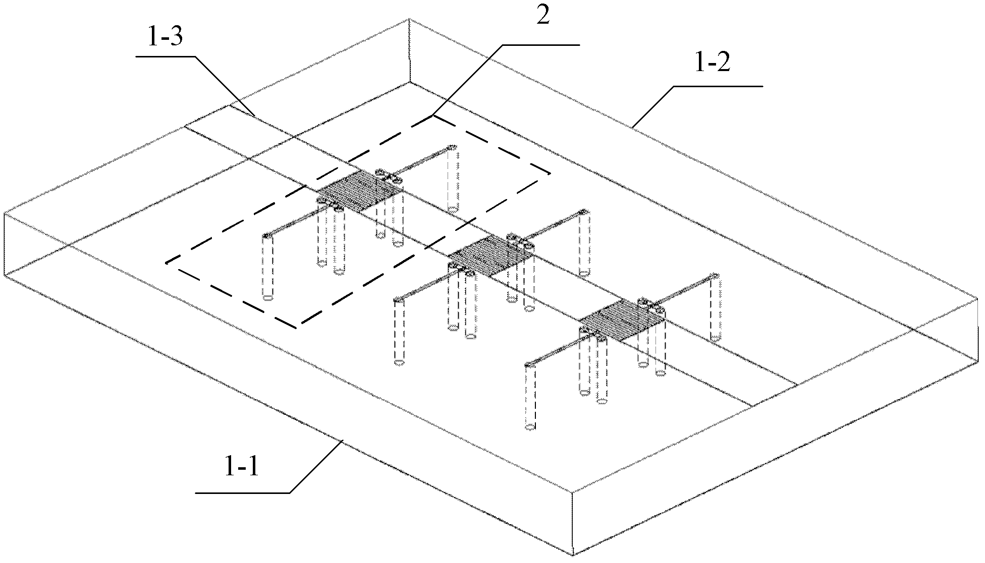
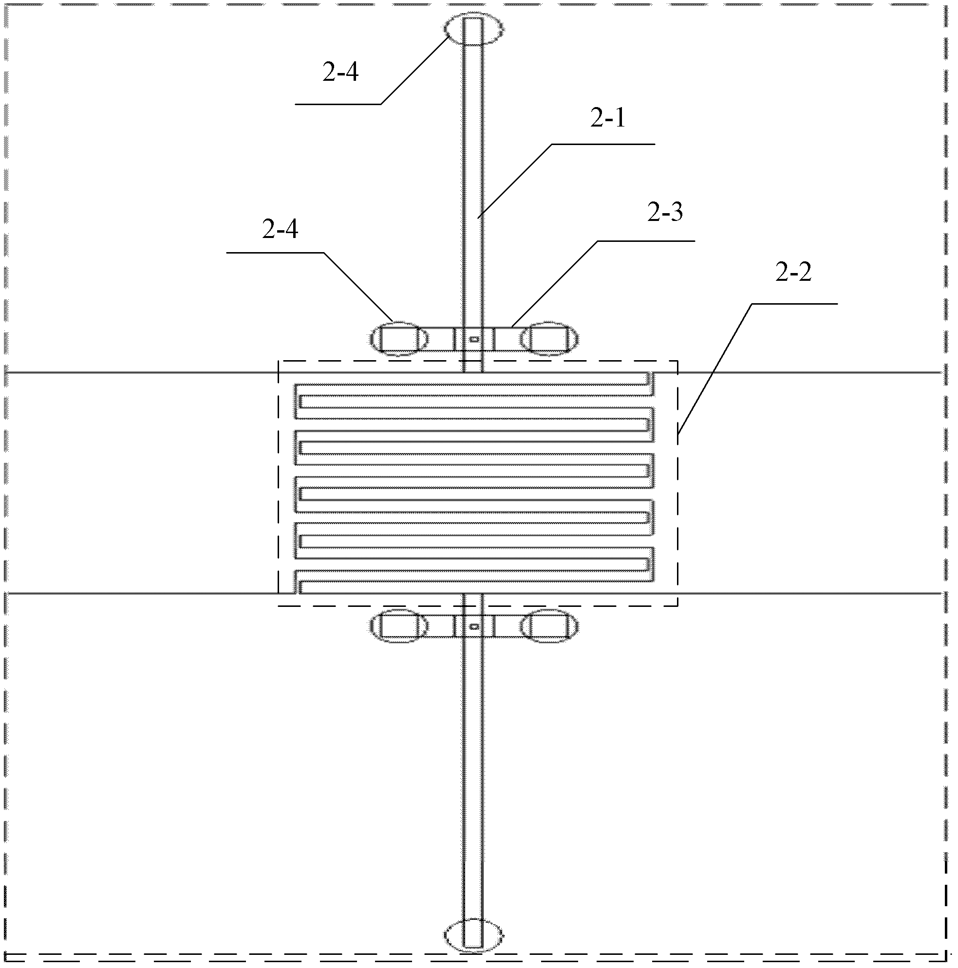
[0017] Specific implementation mode one: combine figure 1 , figure 2 , image 3 , Figure 4 with Figure 5 Describe this embodiment, the MEMS load line type 2 phase shifter based on the left-hand transmission line described in this embodiment, it includes a microstrip line 1 and three groups of phase shifting units 2; the microstrip line 1 includes a ground plate covered with a metal layer 1-1, the base 1-2 and the signal line 1-3, the signal line 1-3 is fixed on the upper surface of the base 1-2, and is located in the middle of the base 1-2 along the width direction, the signal line 1-3 is divided into Four sections, each adjacent two sections are electrically connected through a phase shifting unit 2;

[0018] The phase shifting unit 2 includes a stub 2-1, an interdigitated capacitor 2-2, a MEMS switch 2-3 and a cylindrical metal via 2-4; the stub 2-1 and the interdigitated capacitor 2-2 form a left-hand transmission line the structural unit;

[0019] A stub 2-1 and a...

specific Embodiment approach 2

[0023] Embodiment 2: The difference between this embodiment and the MEMS load line type 2 phase shifter based on the left-hand transmission line described in Embodiment 1 is that the distance between the centers of adjacent single phase shifting units 2 is 800 μm.

specific Embodiment approach 3

[0024] Embodiment 3: This embodiment is different from the MEMS load line type 2 phase shifter based on the left-hand transmission line described in Embodiment 1 in that the length of the phase shifter is 3.0mm, the width is 1.8mm, and the height is 0.234mm .


PUM


Abstract

The invention discloses a micro electronic mechanical system (MEMS) load line type 2-bit phase shifter based on a left-handed transmission line, and particularly relates to an MEMS load line type 2-bit phase shifter in order to solve the problems of small phase shift amount and large switching quantity of MEMS switches in the 2-bit phase shifter. A microstrip line comprises a ground plate, a base and a signal wire, wherein a metal layer is covered on the ground plate; the signal wire is fixed on the upper surface of the base and positioned at a middle position of the base along the width direction, and is divided into four sections, and each two adjacent sections are electrically connected with each other through a phase-shifting unit; the phase-shifting unit comprises stub lines, an interdigital capacitor, MEMS switches and a cylindrical metal through hole; and a stub line and an MEMS switch are arranged at two ends of the interdigital capacitor respectively, one end of the stub line is connected with the center of one end of the interdigital capacitor, and a cube contact point is arranged in the middle of the lower surface of a bridge of the MEMS switch and is suspended above the stub line. The MEMS load line type 2-bit phase shifter is used for controlling phase changes of signals.

Description

technical field [0001] The invention relates to a MEMS load line type 2 phase shifter, in particular to a MEMS load line type 2 phase shifter based on a left-hand transmission line. Background technique [0002] The phase shifter is used to control the phase change of the signal. It is the basic component of the wireless communication system and the key component of the phased array radar, microwave and millimeter wave receiver and transmitter. According to the different signal delay mechanism, it can be divided into reflection linear phase shifter, switch linear phase shifter and load linear phase shifter. Among them, the load linear phase shifter controls the phase difference under different load conditions by adjusting the load impedance value. Currently, traditional phase shifters are generally implemented based on PIN diodes, EFT switches or ferrite materials. With the development of information technology, the operating frequency of communication systems such as mobi...

Claims


Application Information

Patent Timeline
Patent Type & Authority Applications(China)
IPC IPC(8): H01P1/18B81B7/02
Inventor 傅佳辉陈鹏吴群张狂杨国辉孟繁义
Owner HARBIN INST OF TECH
Learn More