Design method of low-profile dual-polarized tile antenna unit adopting T-shaped microstrip feeding

An antenna unit and microstrip feeding technology, which is applied to antenna unit combinations with different polarization directions, antenna coupling, radiating element structure and other directions to achieve the effects of reducing matching difficulty, high polarization purity, and low input impedance

Inactive Publication Date: 2012-07-11
THE 724TH RES INST OF CHINA SHIPBUILDING IND
View PDF3 Cites 18 Cited by
  • Summary
  • Abstract
  • Description
  • Claims
  • Application Information

AI Technical Summary

Problems solved by technology

Therefore, the above antenna forms are no

Method used


Image

  • Design method of low-profile dual-polarized tile antenna unit adopting T-shaped microstrip feeding
  • Design method of low-profile dual-polarized tile antenna unit adopting T-shaped microstrip feeding
  • Design method of low-profile dual-polarized tile antenna unit adopting T-shaped microstrip feeding

Examples


Embodiment 1

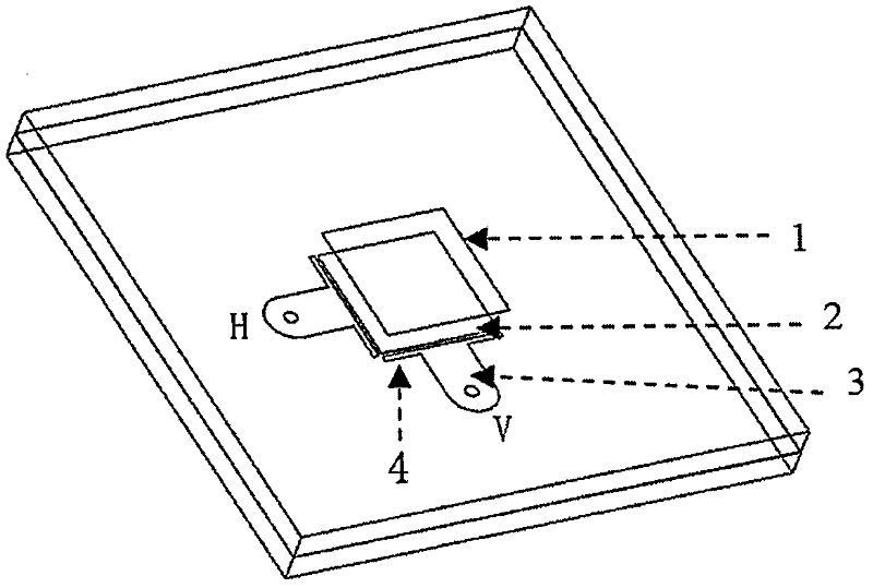
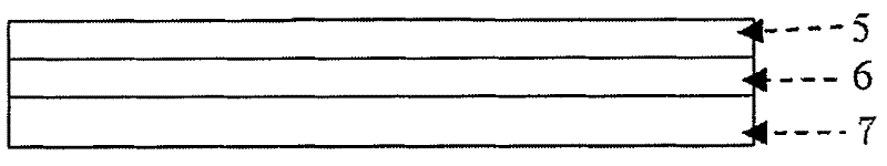
[0030] see figure 1 , figure 2 , a T-shaped microstrip-fed low-profile dual-polarized tile antenna unit. The whole antenna includes: a parasitic antenna unit 1 at the top layer, an exciting antenna unit 2 at the bottom layer and a supporting metal plate 7 . The parasitic antenna unit on the top layer is a patch antenna, the dielectric constant of the microstrip board 5 is 2.55, and the thickness is 1.524mm; The constant is 2.55 and the thickness is 1.524mm. The back of the antenna is supported by a metal plate 7 . The antenna contains two kinds of orthogonally polarized radiating elements, which are represented as figure 1 The horizontal (H), vertical (V) polarization definitions are shown.

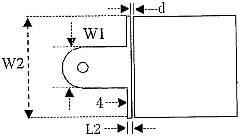
[0031] see image 3 , the excitation antenna unit at the bottom layer is coupled and fed through the T-shaped microstrip line on the same layer, and the distance d between the patch unit and the T-shaped feeding network is 0.2mm. The microstrip patch unit is square, with a size of...

Embodiment 2

[0040] Preferred embodiment 2 of the present invention is as Figure 10 , is a 4×8 dual-polarized antenna array for X-band applications. The antenna array is composed of 32 array elements arranged periodically along the aperture, and the horizontal and vertical element spacing is 15mm. Each unit has both horizontal and vertical polarization. The antenna array can increase the antenna gain, together with amplitude and phase weighting, it can realize the scanning function.


PUM

PropertyMeasurementUnit
Thicknessaaaaaaaaaa
Sizeaaaaaaaaaa
Line widthaaaaaaaaaa

Abstract

The invention relates to a design method of a low-profile dual-polarized tile antenna unit adopting T-shaped microstrip feeding. The design method is characterized in that an antenna patch unit adopts a T-shaped microstrip line for coupled feeding, a feeding network and the patch unit are located in one layer, and two polarizing and feeding networks are arranged; and a parasitic unit is located just above an excitation unit. The antenna has capability of suppressing antenna system low-frequency signal interference, and has standing wave ratio smaller than 1.8 and cross polarization level smaller than -17dB in 20% relative bandwidth; and the T-shaped microstrip line is adopted for coupled feeding as well as is located in one plane with an antenna radiation unit, thus the thickness of the antenna unit is significantly reduced. The obtained antenna unit not only can be used as a unit of a tile type array antenna, but also can be independently used as a transceiver antenna of a polarization diversity system.

Description

Technical field [0001] The invention relates to a design method for a T-shaped microstrip feeding low-profile dual-polarization tile antenna unit. Specifically, the patch unit is coupled and fed through the T-shaped microstrip line on the same layer, dual-polarized, and a parasitic unit is added above to widen the bandwidth of the microstrip patch antenna. The antenna of the invention has the advantages of simple feeding structure and can suppress low-frequency signal interference. Not only can it be used as a unit of a tiled array antenna, but it can also be used independently as a receiving and transmitting antenna of a polarization diversity system. Background technique [0002] The tile-integrated antenna array module is horizontally integrated and vertically assembled (Griffin D W, Parfitt A J. Electromagnetic design aspects of packages for monolithic microwave integrated circuit-based arrays with integrated antenna elements[J]. IEEE Transactions Oil Antennas and Propa...

Claims


Application Information

Patent Timeline
IPC IPC(8): H01Q1/38H01Q1/52H01Q21/24
Inventor 高国明常德杰陈文俊徐勤
Owner THE 724TH RES INST OF CHINA SHIPBUILDING IND
Why Eureka
Try Eureka