Power converting apparatus for an electric car

A power conversion device and power converter technology, applied in electric vehicles, power consumption devices, output power conversion devices, etc., can solve problems such as burnout, expansion of faulty parts of power converters, heating of synchronous machines, etc., to reduce the burden Effect

Inactive Publication Date: 2012-07-11
MITSUBISHI ELECTRIC CORP
View PDF4 Cites 5 Cited by
  • Summary
  • Abstract
  • Description
  • Claims
  • Application Information

AI Technical Summary

Problems solved by technology

Therefore, if this state is left unattended, a large short-circuit current will flow, so there is a possibility that the faulty part of the power converter will expand, or since the short-circuit current also flows in the synchronous machine, the synchronous machine may generate heat or burn out. possibility

Method used


Image

  • Power converting apparatus for an electric car
  • Power converting apparatus for an electric car
  • Power converting apparatus for an electric car

Examples


Embodiment approach 1

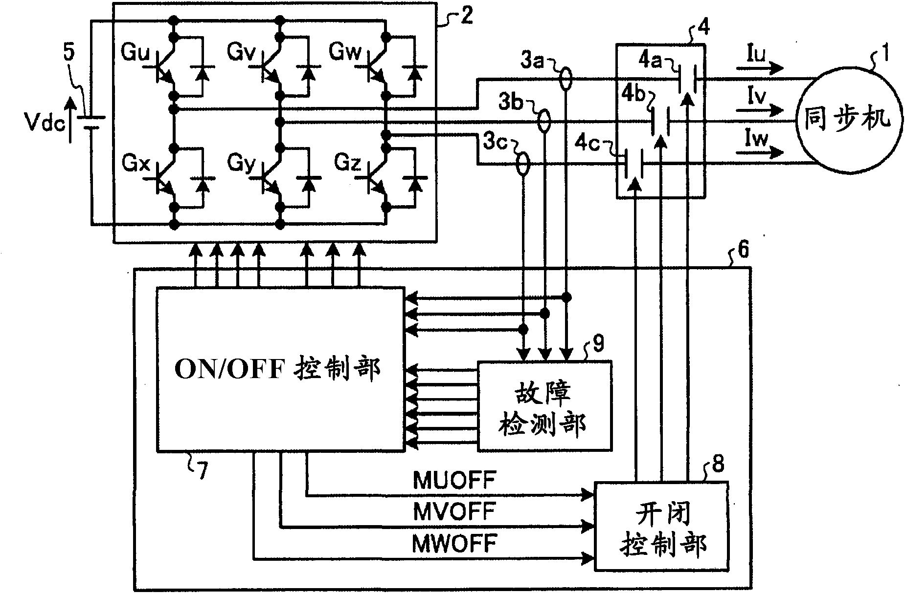
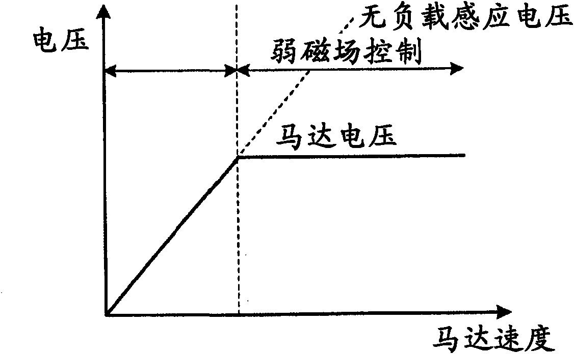
[0027] figure 1 is a diagram showing a configuration example of a power conversion device for an electric vehicle according to Embodiment 1 of the present invention, figure 2 It is a graph showing the relationship between the motor voltage and the no-load induced voltage of the synchronous machine 1 . figure 1The power conversion device of the electric vehicle shown has: a power converter 2, which is connected to a DC power supply 5 and drives the synchronous machine 1; and the control unit 6 controls the operation of the power converter 2 and the opening control of the switch unit 4 .

[0028] The power converter 2 is composed of three switching (hereinafter simply referred to as "SW") elements (U-phase upper arm element Gu, V-phase upper arm element Gv, and W-phase upper arm element Gw) of the positive side arm, and A bridge circuit of three SW elements (U-phase lower arm element Gx, V-phase lower arm element Gy, and W-phase lower arm element Gz) of the negative side arm ...

Embodiment approach 2

[0077] Figure 8 is a diagram showing one configuration of a power conversion device for an electric vehicle according to Embodiment 2 of the present invention, Figure 9 It is a figure showing another structure of the electric power conversion apparatus of the electric vehicle concerning Embodiment 2 of this invention, Figure 10 is used to illustrate the Figure 8 as well as Figure 9 The flow chart of a series of operations from when an abnormality occurs in the power converter 2 to opening the switch 4 is shown. In addition, the same code|symbol is attached|subjected to the same part as 1st Embodiment, the description is abbreviate|omitted, and only a different part is described.

[0078] The point of difference from Embodiment 1 is that only two phases (for example, U-phase and V-phase) are provided with switching units. Therefore, the opening and closing control unit 24 such as Figure 8 As shown, it is sufficient to output only 2-phase control signals. In addition...


PUM


Abstract

Disclosed is a power converting apparatus which is provided with a power converter (2) which has switching elements (Gu - Gz) and drives a synchronous machine (1), an opening / closing unit (4), current detectors (3a - 3c), and a control unit (6) which performs on / off control of the switching elements (Gu -Gz) and opening / closing control of the opening / closing unit (4) based on the currents detected by the current detectors (3a - 3c). The control unit (6) has a fault detection unit (9) which detects whether there is a bridging fault in any of the switching elements (Gu - Gz) and outputs a signal indicating the detection results; an ON / OFF control unit (7) which, when a first phase (e.g. the U phase) involves a bridging fault, sets one of the switching elements constituting another phase (the V phase or the W phase) to an on operating state, and also outputs a signal to open the opening / closing unit (4); and an opening / closing control unit (8) which, when a second phase (e.g. the W phase) has a switching element set to an on operating state by the ON / OFF control unit, for the third phase (e.g. the V phase) other than the first phase or the second phase, opens the V phase opening / closing unit (4b) which is connected to the third phase.

Description

technical field [0001] The present invention relates to a power conversion device for driving a synchronous machine used in electric vehicles including railway vehicles and electric vehicles, and more particularly to a power conversion device including a switch between the synchronous machine and the power converter. Background technique [0002] Compared with induction motors that have been widely used in various fields in the past, synchronous machines have the following advantages. Since the magnetic flux generated by the magnets built in the rotor is established, no field current is required. Current flows through the rotor, so there is no secondary copper loss. Therefore, the use of synchronous machines has been studied in order to improve efficiency in electric vehicles. [0003] Electric vehicles travel by connecting multiple vehicles equipped with power converters and synchronous machines to form a formation. Therefore, even if a short-circuit fault occurs in the sw...

Claims


Application Information

Patent Timeline
Patent Type & Authority Applications(China)
IPC IPC(8): H02M7/48H02P27/06B60L3/00B60L9/18H02P25/022
CPCB60L2200/26H02M1/32B60L3/003H02M7/53875B60L2220/14H02H7/0838H02H7/122H02H7/1225H02P29/027Y02T10/64H02H7/08H02M7/48
Inventor 河野雅树草野健一山下良范北中英俊畠中启太
Owner MITSUBISHI ELECTRIC CORP
Why Eureka
Try Eureka