Radio frequency power amplifier with linearizing predistorter

A power amplifier, predistorter technology, applied in the direction of radio frequency amplifiers, amplifiers with semiconductor devices/discharge tubes, high frequency amplifiers, etc. Problems such as driving voltage

Active Publication Date: 2012-07-11
SKYWORKS SOLUTIONS INC
View PDF5 Cites 8 Cited by
  • Summary
  • Abstract
  • Description
  • Claims
  • Application Information

AI Technical Summary

Problems solved by technology

However, increasing current alone typically does not provide sufficient overdrive voltage at the gate-source junction to assume a linear output current signal18
A technique known as degeneration can be combined with the above-mentioned increased current technique to further promote linearity, but this degradation prevents the use of the bias voltage signal 22 as amplifier gain control
Also, the increased current in the mobile radiotelephone handset power amplifier tends to drain the battery faster

Method used


Image

  • Radio frequency power amplifier with linearizing predistorter
  • Radio frequency power amplifier with linearizing predistorter
  • Radio frequency power amplifier with linearizing predistorter

Examples


Embodiment Construction

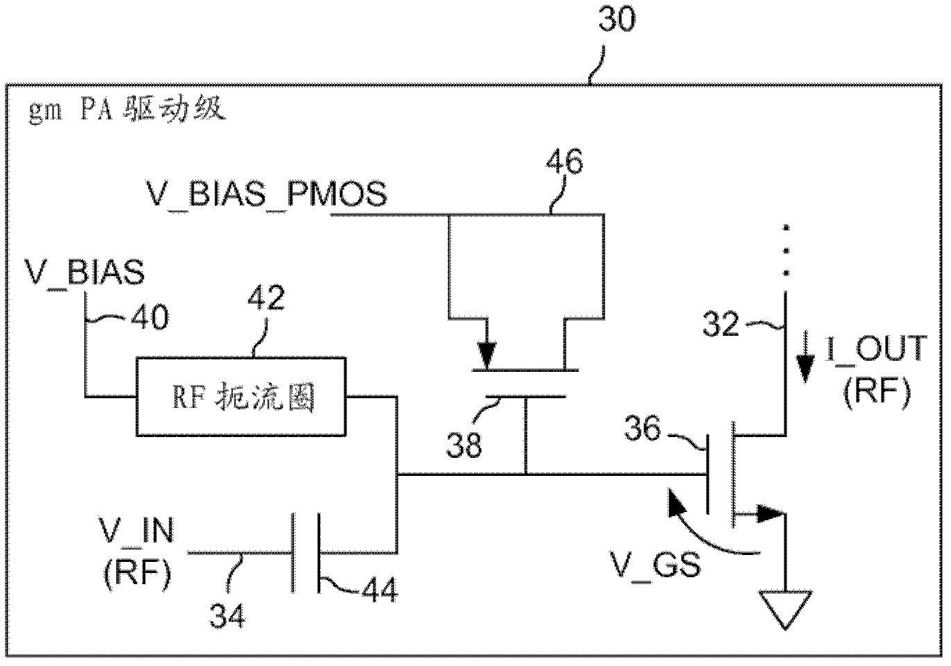
[0017] Such as image 3 As shown, the transconductance (g) of this type of RF power amplifier can be commonly included in, for example, some types of mobile wireless telephone handsets. m The amplifier circuit 30 included in the) stage outputs an RF current signal 32 (I_OUT) in response to the RF input voltage signal 34 (V_IN). The amplifier circuit 30 includes an amplifier MOSFET 36 and a predistorter MOSFET 38. in image 3 In the illustrated embodiment, the amplifier MOSFET 36 is an n-channel (NMOS) device, and the predistorter MOSFET 38 is a p-channel (PMOS) device.

[0018] The gate terminal of the amplifier MOSFET 36 is coupled to the first bias voltage signal 40 (V_BIAS) via the RF choke 42. The gate terminal of the amplifier MOSFET 36 is also coupled to the input voltage signal 34 via the linear coupling capacitor 44. The source terminal of the amplifier MOSFET 36 is connected to ground. The drain terminal of the amplifier MOSFET 36 is connected to a current source circuit...


PUM


Abstract

A power amplifier circuit includes an amplifier MOSFET and a predistorter MOSFET. The predistorter MOSFET source and drain are connected together, and the predistorter MOSFET is connected between the gate of the amplifier MOSFET and a second bias voltage signal. This biasing of the predistorter MOSFET causes it to provide a nonlinear capacitance at the gate of the amplifier MOSFET. The combined non-linear capacitances of the amplifier MOSFET and predistorter MOSFET provide predistortion that promotes cancellation of the distortion or nonlinearity contributed by the amplifier MOSFET alone.

Description

Background technique [0001] Radio frequency (RF) transmitters, such as those included in mobile radiotelephone handsets (also called cellular phones) and other portable radio transceivers, often include power amplifiers. The power amplifier is usually the last stage of the transmitter circuit. In some types of transmitters, it is important to achieve linear power amplification. However, various factors may hinder linear operation. For example, in some types of mobile radio telephone handsets, such transmitters are usually included, in which the power amplifier receives the output of an up-conversion mixer, which usually outputs a relatively large signal that can reduce the power The amplifier is driven into non-linear operation. Increasing the power amplifier current is a technique used to promote linear operation in such transmitters, but it does not work well in all situations. [0002] As shown in Figure 1-2, in some types of mobile radio telephone handsets of this type of ...

Claims


Application Information

Patent Timeline
Patent Type & Authority Applications(China)
IPC IPC(8): H04B1/04H03F1/32
CPCH03F3/245H03F1/3205H03F1/3241H04B2001/0425H03F3/193H03F1/0261H03F2200/18H03F2200/451H03F2200/408H03F1/3276H03F1/32H03F3/04H03F3/082H03F3/189H03F3/19H04B1/04
Inventor H.R.阿米尔费罗兹库西B.阿加瓦尔H.阿克约尔
Owner SKYWORKS SOLUTIONS INC
Why Eureka
Try Eureka