Multi-layer composite T-shaped pipe separator and separation method for separating two-phase flow or multiphase flow

A multi-layer composite and separation method technology, applied in separation methods, chemical instruments and methods, immiscible liquid separation, etc., can solve the problem that the complete separation point of the separator is not easy to control, etc., and achieve simple structure, low cost, and small volume Effect

Inactive Publication Date: 2012-07-18
CHANGZHOU UNIV
View PDF2 Cites 13 Cited by
  • Summary
  • Abstract
  • Description
  • Claims
  • Application Information

AI Technical Summary

Problems solved by technology

[0005] The technical problem to be solved in the present invention is: the present invention utilizes the advantages of the above-mentioned invention application and overcomes the above-mentioned shortcomings, provides an improved multi-la

Method used


Image

  • Multi-layer composite T-shaped pipe separator and separation method for separating two-phase flow or multiphase flow
  • Multi-layer composite T-shaped pipe separator and separation method for separating two-phase flow or multiphase flow
  • Multi-layer composite T-shaped pipe separator and separation method for separating two-phase flow or multiphase flow

Examples


Embodiment 1

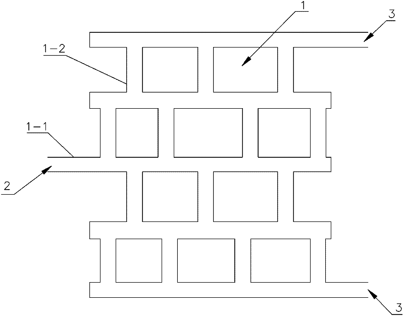
[0030] Embodiment 1 adopts figure 1 The shown multi-layer composite T-tube separator for gas-liquid two-phase flow separation

[0031] The gas-liquid two-phase flow system is composed of air and water. figure 1 The multi-layer composite T-shaped tube separator with a 4-layer structure as shown includes four composite T-shaped tube layers 1, and two adjacent composite T-shaped tube layers 1 are placed vertically or obliquely or horizontally, and the composite T-shaped tube Layer 1 includes two main pipes 1-1 and at least two intermediate connecting pipes 1-2 vertically connected between the two main pipes 1-1, and a common main pipe 1-1 is shared between adjacent composite T-shaped pipe layers 1, The multi-layer composite T-shaped pipe separator for the separation of two-phase flow or multi-phase flow also has an inflow port 2 for the inflow of the mixture and two outflow ports 3 for the outflow of the separated fluid, on each main pipe 1-1 The inflow port 2 for mixture inflo...

Embodiment 2

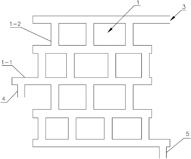
[0033] Embodiment 2 adopts figure 2 The shown multi-layer composite T-tube separator for liquid-liquid two-phase flow separation

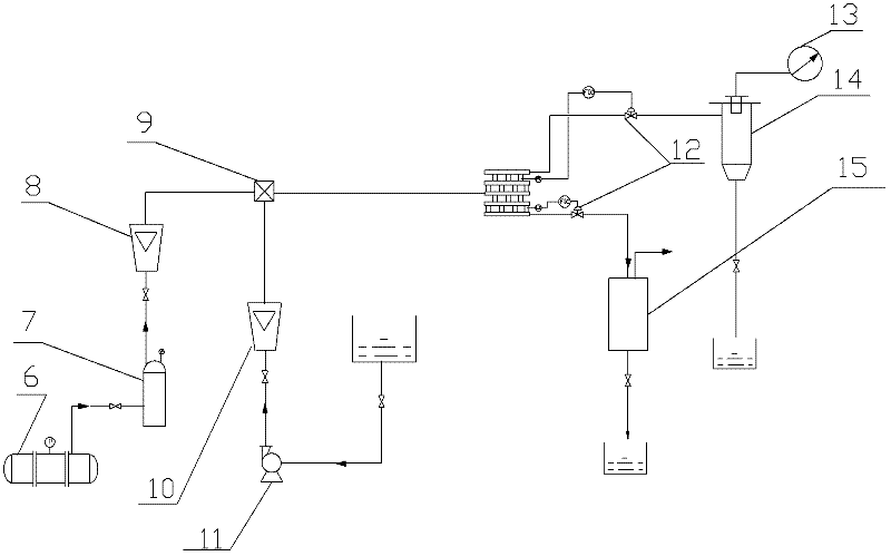
[0034] Will image 3 The air supply system of the medium-use compressor is transformed into a system of kerosene delivery by an oil pump, and the separation and metering system of the two outlets after the separation of the multi-layer composite T-tube separator is correspondingly transformed. image 3 The device can also be used to test the phase separation characteristics of liquid-liquid two-phase flow at the multi-layer composite T-shaped pipe. The liquid-liquid two-phase flow system is composed of kerosene and water. figure 2 The multi-layer composite T-shaped tube separator with a 4-layer structure as shown includes four composite T-shaped tube layers 1, and two adjacent composite T-shaped tube layers 1 are placed vertically or obliquely or horizontally, and the composite T-shaped tube Layer 1 includes two main pipes 1-1 and at least two...


PUM


Abstract

The invention discloses a multi-layer composite T-shaped pipe separator for separating two-phase flow or multiphase flow. The multi-layer composite T-shaped pipe separator comprises an inflow hole, two outflow holes and at least two composite T-shaped pipe layers, wherein a mixture flows into the separator through the inflow hole; the separated fluid can flow out of the separator through the outflow holes; each composite T-shaped pipe layer comprises two main pipes and at least two intermediate connecting pipes which are vertically communicated between the two main pipes; and one main pipe is shared between every two adjacent composite T-shaped pipe layers. The invention also provides a separation method adopting the multi-layer composite T-shaped pipe separator. In the separation method, automatic control valves arranged at the two outflow holes are used for controlling the fluid allocation proportion of the two outflow holes by respectively taking liquid level, pressure or two-phase volume fraction as a feedback control signal, so that the two-phase flow can be completely separated from each other or almost completely separated from each other. The multi-layer composite T-shaped pipe separator is simple in structure, small in volume and low in cost, and leads two phases to be separated completely according to an ideal separation model; and meanwhile, the multi-layer composite T-shaped pipe separator has a pipe-type structure, thus being more convenient to replace and maintain.

Description

technical field [0001] The invention relates to the technical field of two-phase flow or multiphase flow separation, in particular to a multi-layer composite T-shaped tube separator and a separation method for two-phase flow or multiphase flow separation. Background technique [0002] Two-phase flows such as gas-liquid, liquid-liquid, liquid-solid, gas-solid and multi-phase flows such as gas-liquid-solid are common in chemical industry, metallurgy, energy, mining, food and home appliance industries. In order to improve the economy and safety of industrial processes and to obtain a single-phase product, these different phases often need to be separated by certain methods. [0003] Traditional separators of this type mainly include separation tanks, settling tanks, and cyclone separators. However, the separation tank or settling tank is generally bulky. If it is the oil-gas and oil-water separation in offshore oil fields, a large offshore platform must be erected, which not o...

Claims


Application Information

Patent Timeline
IPC IPC(8): B01D17/02B01D19/00B01D43/00B01D49/00
Inventor 杨利民石贤锋魏科年王珈浩陈群
Owner CHANGZHOU UNIV
Why Eureka
Try Eureka