
Manufacturing process of shaft bodies of carbon-fiber arrow shafts

A manufacturing process, carbon fiber technology, applied in the direction of layered products, glass/slag layered products, synthetic resin layered products, etc., can solve problems such as poor deflection, affecting flight trajectory, arrow shaft breakage, etc., and achieve easy production and operation Sexuality, reduction of production process, and improvement of production efficiency

Active Publication Date: 2012-07-18
NANTONG ZHONGDING COMPOSITE MATERIAL
View PDF5 Cites 14 Cited by
  • Summary
  • Abstract
  • Description
  • Claims
  • Application Information

AI Technical Summary

Problems solved by technology

[0007] Disadvantages of poor straightness: it will affect the flight trajectory. Such a defect is fatal. When the user is hunting or shooting, the arrow will be affected by factors such as wind resistance when moving in the air. Experienced athletes will seek the best Arrow shaft with the best flight path for the most accurate shooting target
[0009] The disadvantage of poor deflection is that since the arrow shaft is placed in the middle of the bow when it is fired, it is under a lot of stress when it is released and before the arrow enters the target
If the deflection of the arrow shaft is not enough, it will directly cause the arrow shaft to break and break

Method used

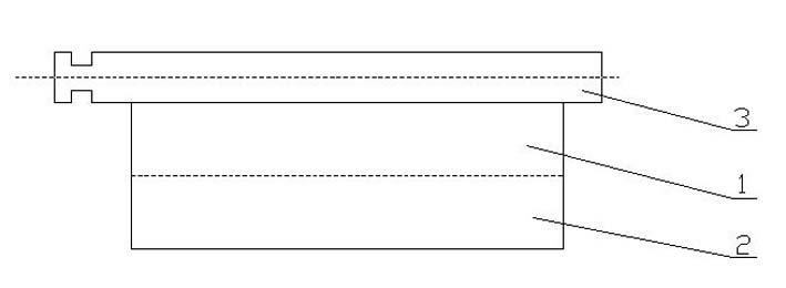
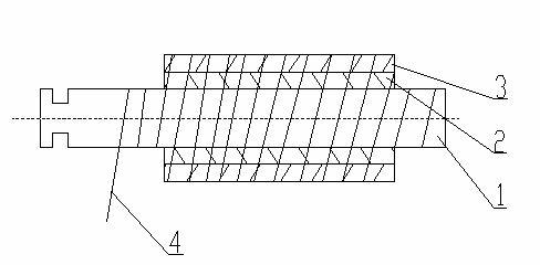

Image

  • Manufacturing process of shaft bodies of carbon-fiber arrow shafts
  • Manufacturing process of shaft bodies of carbon-fiber arrow shafts
  • Manufacturing process of shaft bodies of carbon-fiber arrow shafts

Examples


Embodiment 1

[0029] The production specifications are: ID6.2*OD7.5*L762, the deflection is 300Spine, and the straightness is ≤0.004";

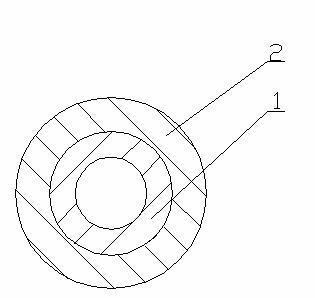
[0030] Arrow shaft structure of present embodiment is as figure 1 As shown: the rod body is made of a bottom layer 1 and a coating layer 2, two layers of fabric impregnated with resin and epoxy resin are laminated and wound, and made into a hollow tubular structure with a constant inner and outer diameter. In this embodiment, the inner diameter of the finished product is 6.2 mm, and the outer diameter is 7.5 mm.

[0031] The fabric of the bottom layer 1 is a whole block with the warp and weft yarns as coordinates, and is cut into rectangular and sheet-like pre-impregnated resin plain weave fabrics at 40-60°, and the weight of the resin is 55% of the weight of the glass fiber; the bottom layer 1 is a rectangle, sheet Shaped pre-impregnated resin plain fabric is wound with the long side as the length of the rod body to form a hollow tubular laminate. After ...


PUM


Abstract

The invention discloses a manufacturing process of shaft bodies of carbon-fiber arrow shafts. The manufacturing process is characterized by comprising the following steps of: pre-manufacturing plain glass fiber woven fabric and uni-directional carbon fiber weftless fabric which are dipped with resin; according to the different flexibility requirements of the carbon-fiber arrow shafts, calculatingthe plain glass fiber woven fabric and the uni-directional carbon fiber weftless fabric which need to be used, then winding the plain glass fiber woven fabric and the uni-directional carbon fiber weftless fabric in a layer-by-layer manner by adopting the direction of the central longitudinal axis of a core-rod mold as the gluing direction of the long edge of a fabric blank; integrally winding BOPP (Biaxially Oriented Polypropylene) belts on the wound core-rod mold so as to fix the fabrics; carrying out sectional curing treatment on the mold wound with the belts; and finally demolding, cuttingand grinding to obtain a finished product. The arrow shafts manufactured by using the process have the advantages that the linearity of more than 99% arrow shafts is within + / -0.004'(+ / -0.1mm); the flexibility is consistent; the production operation is simple and convenient; and the production efficiency is improved.

Description

technical field [0001] The invention relates to a manufacturing process for an arrow shaft body, in particular to a manufacturing process for making a carbon fiber arrow shaft body by winding or laminating technology. Background technique [0002] Arrow shafts have always been an indispensable tool for hunting and shooting sports, and are mainly composed of shafts, arrows, and blades. There are many types of arrow shafts, mainly divided into 473 and 578 types of fabrics. [0003] The earliest arrow shafts were made of solid wood. Later, with the evolution of the market, hollow metal shafts appeared. Later, hollow structures became the norm for shafts. With the continuous development of materials science, glass fiber or carbon materials were used instead of metal. Rod bodies have also become very standardized. [0004] However, due to the inherent characteristics of carbon fiber or glass fiber materials, it is difficult to control the straightness and deflection of arrow s...

Claims


Application Information

Patent Timeline
Patent Type & Authority Applications(China)
IPC IPC(8): B32B1/08B32B17/04B32B27/04B32B27/38
Inventor 惟学周加其
Owner NANTONG ZHONGDING COMPOSITE MATERIAL
Learn More