Supercharge Your Innovation With Domain-Expert AI Agents!

Pneumatic-propelling solid and liquid separation device

A solid-liquid separation, pneumatic propulsion technology, applied in the direction of dewatering/drying/concentrating sludge treatment, can solve the problems of uneven heating, difficult to heat the sludge, destroy the colloidal structure of the sludge and release water, etc., and achieve a high dehydration rate. , improve the effect of propulsion

Inactive Publication Date: 2012-07-18
AMCON FUJIAN ENVIRONMENT PROTECTION EQUIP CO LTD
View PDF8 Cites 42 Cited by
  • Summary
  • Abstract
  • Description
  • Claims
  • Application Information

AI Technical Summary

Problems solved by technology

Obviously, to heat the sludge in the sludge tank to achieve the above effect, the energy consumed is very large, and the electric heating band is set on the wall of the sludge tank. For the whole tank of sludge There is a problem of uneven heating, the sludge near the tank wall is easy to be heated, and the sludge in the center of the tank is difficult to be heated
Therefore, it is difficult to achieve the effect of destroying the colloidal structure of the sludge and releasing water by cell rupture by setting a heating belt on the sludge tank wall to preheat the sludge, and the energy consumption is large, and the dehydration cost is high. Poor practicality

Method used


Image

  • Pneumatic-propelling solid and liquid separation device
  • Pneumatic-propelling solid and liquid separation device
  • Pneumatic-propelling solid and liquid separation device

Examples


Embodiment Construction

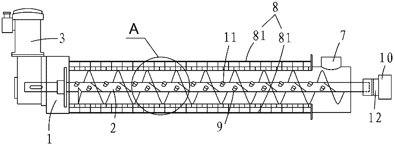
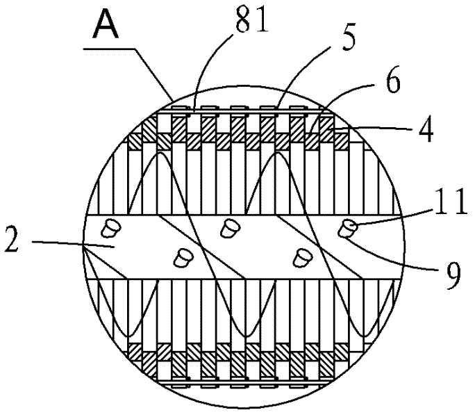
[0023] Such as figure 1 and figure 2 As shown, a pneumatic propulsion solid-liquid separation device includes a sludge discharge port 1, a screw shaft 2, a motor 3, a fixed ring 4, an adjustment block 5, a moving ring 6, a sludge inflow port 7 and a fixed bracket 8. The fixing bracket is composed of a plurality of fixing rods 81 . Such as figure 2 As shown, the spacer set ring 4 and the moving ring 6 are set on the blades of the screw shaft 2, the fixed ring is fixed by a fixed rod 81, the adjustment block 6 can be a gasket, and the adjustment block 5 makes each The distance between two adjacent fixed rings 4 is slightly larger than the thickness of the moving ring 6 , and the screw shaft 2 is driven by the motor 3 to rotate at a low speed.

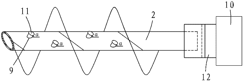
[0024] Such as image 3 As shown, a pneumatic propulsion type solid-liquid separation device, the central axis of the screw shaft 2 is hollow and a plurality of air outlets 9 are arranged on the shaft wall of the central axis of the...


PUM


Abstract

The invention discloses a pneumatic-propelling solid and liquid separation device, which comprise a spiral shaft, wherein the center shaft of the spiral shaft is hollow; the shaft wall of the center shaft is provided with plural air outlets; one end of the spiral shaft is communicated with an air source; a valve is arranged on the air outlet; and the air source and the valve are opened to outwards release airflow with pressure. The pneumatic-propelling solid and liquid separation device has the advantages of simple structure and strong and powerful progressive driving force, various types of sludge can be smoothly processed, and the sludge processing efficiency, the sludge processing amount and the sewage dewatering rate are improved.

Description

【Technical field】 [0001] The invention relates to a solid-liquid separation device, in particular to a pneumatic propulsion type solid-liquid separation device. 【Background technique】 [0002] Existing solid-liquid separation device, such as the Chinese utility model patent whose publication number is CN2762865, "laminated spiral filter" disclosed on March 8, 2006, includes a screw shaft, and the outer diameter of the blade of the screw shaft is The face cover has a plurality of loop laminations, and the multiple loop laminations are composed of a fixed ring, a moving ring and an adjustment block, and the arrangement of the cycle laminations is that there are adjustment blocks and a fixed moving ring between every two fixed rings. Adjust the distance between the two fixed rings through the adjustment block. When the screw shaft rotates, the blades on the screw shaft move the moving ring, so that the moving ring and the fixed ring move relative to each other to form a dehydr...

Claims


Application Information

Patent Timeline
IPC IPC(8): C02F11/12
Inventor 郑朝志
Owner AMCON FUJIAN ENVIRONMENT PROTECTION EQUIP CO LTD
Features
  • R&D
  • Intellectual Property
  • Life Sciences
  • Materials
  • Tech Scout
  • Unparalleled Data Quality
  • Higher Quality Content
  • 60% Fewer Hallucinations
Learn More