Automatic cylinder cover locking device and cheese dyeing machine comprising same

An automatic locking and cylinder head technology, applied in the mechanical field, can solve the problems of unfavorable automatic production, time-consuming and labor-intensive labor, and low labor efficiency, so as to improve the level of mechanization and automation, improve production efficiency, and save labor.

Active Publication Date: 2012-07-18
ADVANCED MFG TECH CENT CHINA ACAD OF MASCH SCI & TECH +1
View PDF7 Cites 17 Cited by
  • Summary
  • Abstract
  • Description
  • Claims
  • Application Information

AI Technical Summary

Problems solved by technology

[0005] The present invention aims to provide an automatic cylinder head locking device and a cheese dyeing machine including the device, so as to solve the problem that the manual locking mechanism of the cylinder head in the prior art is labor-intensive, time-consuming, labor-intensive, and has low labor efficiency. Technical issues conducive to the realization of automated production

Method used


Image

  • Automatic cylinder cover locking device and cheese dyeing machine comprising same
  • Automatic cylinder cover locking device and cheese dyeing machine comprising same
  • Automatic cylinder cover locking device and cheese dyeing machine comprising same

Examples


Embodiment 1

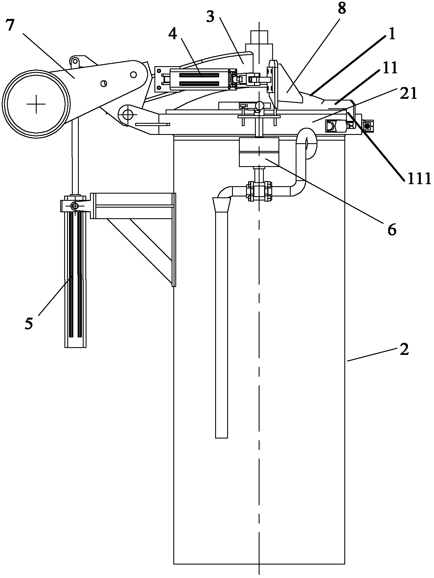
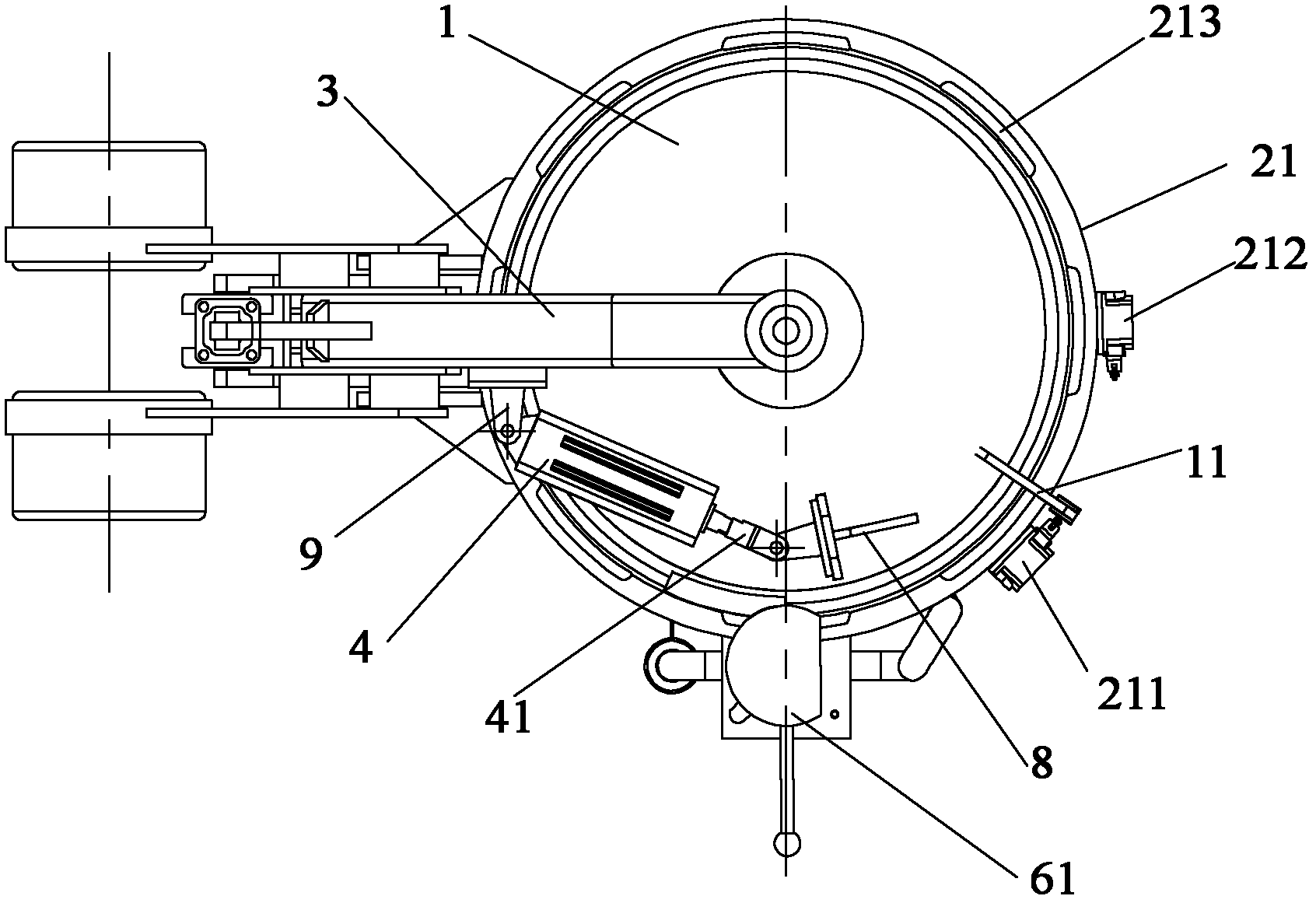
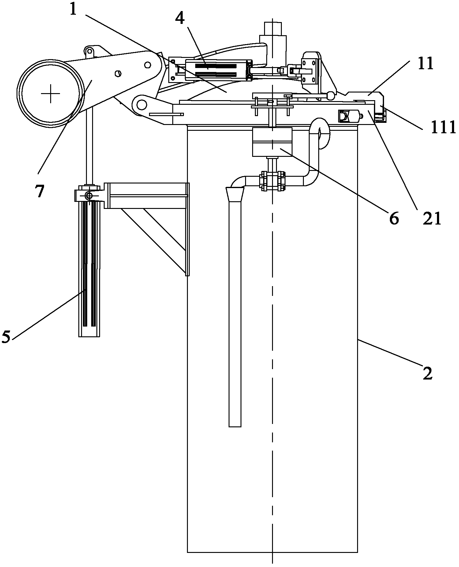
[0029] The cylinder head automatic locking device of the present invention comprises a cylinder head 1 and a cylinder body 2, the cylinder head 1 is provided with teeth 12 uniformly distributed along the circumference, and the upper end circumference of the cylinder body 2 is provided with a hoop supporting the cylinder head 1 21. The clamp 21 has an annular groove for accommodating the tooth 12 and an annular flange above the annular groove. A groove 213 matching the tooth 12 is arranged on the annular flange. A boom 3 is arranged above the cylinder head 1. The boom One end of 3 is pivotally connected to the center of the cylinder head 1 through the central axis, and the other end is pivotally connected to the outer circumference of the clamp 21; the locking cylinder 4 is pivotally connected to the position far from the center of the cylinder head 1 on the boom 3 through the support 9 , the inside of the locking cylinder 4 is provided with a piston rod, one end of the piston r...

Embodiment 2

[0034] The cylinder head automatic locking device of the present invention not only has the structure in Embodiment 1, but also has an unlocked in place travel switch 212 and a locked in place travel switch 211 on the outer edge of the clamp 21, and a bumper on the cylinder head 1. Block 11, one end of the bumper 11 is fixed on the cylinder head 1, and the other end is provided with a bumper 111. When the cylinder head 1 and the cylinder body 2 are closed, the bumper 111 is located between the unlocked limit switch 212 and the locked limit switch. 211, and has the unlocked in place state of touching the unlocked in place travel switch 212 and the locked in place state of touching the locked in place travel switch 211. Unlocked limit switch 212 is electrically connected with the control system. In the unlocked state, the unlocked limit switch 212 sends an unlocked signal to the control system; the locked limit switch 211 is electrically connected with the control system. In the ...

Embodiment 3

[0037] The difference between the cylinder head automatic locking device of the present invention and the second embodiment is that it also includes a pressure relief device, which is electrically connected to the control system to control the maximum pressure value in the cylinder body 2 before the cylinder head 1 is opened. Among them, the pressure relief device preferably includes: a pneumatic ball valve 6 communicated with the inside of the cylinder body 2 and a safety handle 61 arranged on the pneumatic ball valve 6. The safety handle 61 is electrically connected to the control system, and rotates according to the instructions of the control system, so that The pneumatic ball valve 6 communicates with the atmosphere or is isolated from the atmosphere. The safety handle 61 is horizontally arranged on the upper end of the pneumatic ball valve 6. The safety handle 61 has a position above the cylinder head 1; In the tight position, the safety handle 61 is located above the cyl...


PUM


Abstract

The invention provides an automatic cylinder cover locking device and a cheese dyeing machine with the automatic cylinder cover locking device. The automatic cylinder cover locking device is arranged between a cylinder cover and a cylinder body, the cylinder cover is provided with teeth uniformly distributed along the circumference, the upper end of the cylinder body is provided with a clamping hoop supporting the cylinder cover, the clamping hoop is provided with an annular groove for holding the teeth and an annular flange positioned above the annular groove, and the annular flange is provided with slots matched with the teeth. The automatic cylinder cover locking device also comprises a suspension arm and a driving device, wherein the suspension arm is arranged above the cylinder cover, a first end of the suspension arm is pivoted with the cylinder cover, and a second end of the suspension arm is pivoted with the clamping hoop; the driving device is provided with a driving end which is connected to a position on the cylinder cover, deviating from the central axis of the cylinder cover, to drive the cylinder cover to rotate around the central axis of the cylinder cover, so as to lock or unlock the cylinder cover. With the automatic cylinder cover locking device and the cheese dyeing machine with the automatic cylinder cover locking device, labor force is saved, the production efficiency is high, the labor cost is lowered, the mechanization level and automation level of equipment are improved, and realization of automatic production is facilitated.

Description

technical field [0001] The invention relates to the field of mechanical technology, in particular to an automatic cylinder head locking device and a cheese dyeing machine including the device. Background technique [0002] my country is a big textile country, and the textile industry is a traditional pillar industry and occupies a very important position in the national economy. At present, compared with the same industry abroad, the domestic textile industry has long technological process, high labor intensity, labor intensive, low degree of mechanization and automation of production equipment, low production efficiency, and backward overall equipment technology level. At present, the development trend of textile dyeing and finishing industry at home and abroad is high efficiency, energy saving, environmental protection, automation and informatization. [0003] As one of the textile dyeing and finishing equipment, the cheese dyeing machine has a maximum working pressure of...

Claims


Application Information

Patent Timeline
Patent Type & Authority Applications(China)
IPC IPC(8): D06B3/09D06B23/18
CPCD06B23/18D06B5/16D06B23/14F16J13/12F16J13/20
Inventor 单忠德李树广吴双峰沈敏举陈队范刘琳鹿庆福
Owner ADVANCED MFG TECH CENT CHINA ACAD OF MASCH SCI & TECH
Why Eureka
Try Eureka