Jet type sand dredger

A jet-type sand ship technology, applied to special-purpose ships, mechanically driven excavators/dredgers, ships, etc., can solve the problems of high cost, high energy consumption, and impact on quicksand production, so as to reduce operating costs and reduce The effect of large investment cost and large sand mining output

Inactive Publication Date: 2012-07-18
郭景棠 +1
View PDF5 Cites 3 Cited by
  • Summary
  • Abstract
  • Description
  • Claims
  • Application Information

AI Technical Summary

Problems solved by technology

The second-generation jet sand dredger increases the sand mining output by increasing the flow rate of the nozzle. When the flow rate of the nozzle is too large, the water flow rate is large, and the water flow rolls in the sand washing tank. The sand is not easy to settle, and the excessive water flow rate is easy. The sand mixture sucked up by the upper sand nozzle is flushed out of the jet-type sand dredger and returned to the river. The loss rate of sand is high, which affects the production of quicksand
The third-generation jet dredger has a large horsepower, and the LB8250 diesel engine burns 180# heavy oil, which is more economical than the first-generation and second-generation jet dredgers, but it also has the disadvantages of the second-generation jet dredger. In the case of constant diameter, when 3 to 7 pumps are connected in parallel, the total flow of the pumps will increase, and the flow of the nozzles will increase. By increasing the flow of the nozzles, the sand mining output will be increased.
When the flow rate of the nozzle is too large, the water flow is large, and the water flow rolls in the sand washing tank, and the sand is not easy to settle. The excessive water flow rate will easily flush the sand mixture sucked by the upper sand nozzle out of the jet-type sand dredger and return to The river surges, and the loss

Method used


Image

  • Jet type sand dredger
  • Jet type sand dredger
  • Jet type sand dredger

Examples


Embodiment 1

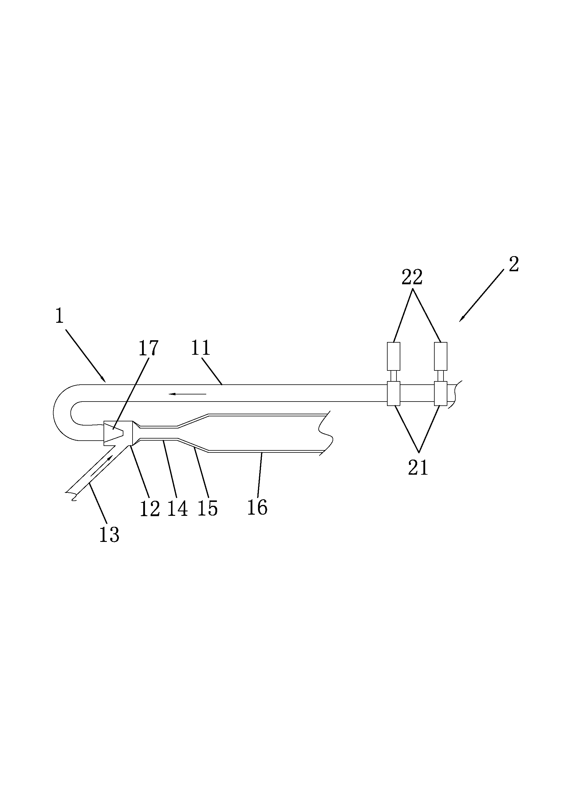
[0045] Such as figure 1 Shown, a kind of jet type dredging ship, it comprises sand pumping equipment, and dredging equipment comprises jet type dredging device 1 and water pump device 2, and jet type dredged device 1 comprises clean water pipe 11, vacuum chamber 12, upper sand nozzle 13 , mixing pipe 14, diffusion pipe 15 and upper sand pipe 16, vacuum chamber 12 is provided with nozzle 17, the water outlet port of clear water pipe 11 is connected with nozzle 17, and the outlet end of upper sand nozzle 13 is connected with vacuum chamber 12, and mixing pipe 14 is respectively Connect with vacuum chamber 12, diffuser pipe 15, diffuser pipe 15 is connected with the inlet end of upper sand pipe 16, water pump device 2 comprises water pump 21 and starting equipment 22, water pump 21 is provided with water inlet and water outlet, and the water outlet of water pump 21 and The water inlet port of the clean water pipe 11 is connected, and the water pump device 2 includes two water pum...

Embodiment 2

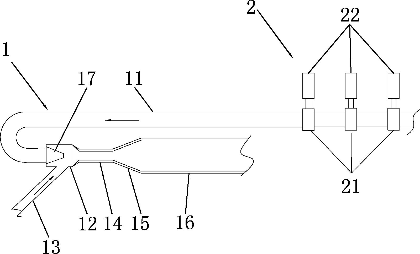
[0051] Such as figure 2 As shown, the difference between this embodiment and Embodiment 1 is that the water pump device 2 of this embodiment includes three water pumps 21 and three starting equipment 22, each water pump 21 is connected to one starting equipment 22, and the water pump 21 and three starting equipment 22 are connected to each other. The water pumps 21 are connected in series. The starting device 22 is a diesel engine.

[0052] When the three water pumps 21 of the water pump device 2 are connected in series, Q 串 = Q 1 = Q 2 = Q 3 , H 串 =H 1 +H 2 +H 3 , and H=P / ρ (ρ is the density of water, 1000kg / m 3 ), it can be seen that P 串 =P 1 +P 2 +P 3 . When three water pumps 21 work in series, the total pressure produced is close to three times the pressure of one water pump 21, the pressure of the vacuum chamber 12 increases, the pressure generated inside and outside the upper sand nozzle 13 increases, and the suction force of the upper sand nozzle 13 incre...

Embodiment 3

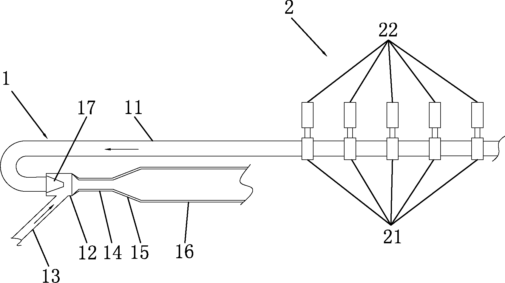
[0055] Such as image 3 As shown, the difference between this embodiment and Embodiment 1 is that the water pump device 2 of this embodiment includes five water pumps 21 and five starting equipment 22, each water pump 21 is connected to one starting equipment 22, and the water pump 21 and five starting equipment 22 are connected to each other. The water pumps 21 are connected in series. The starting device 22 is a diesel engine.

[0056] When the five water pumps 21 of the water pump device 2 are connected in series, Q 串 = Q 1 = Q 2 = Q 3 = Q 4 = Q 5 , H 串 =H 1 +H 2 +H 3 +H 4 +H 5 , and H=P / ρ (ρ is the density of water, 1000kg / m 3 ), it can be seen that P 串 =P 1 +P 2 +P 3 +P 4 +P 5 . When five water pumps 21 work in series, the total pressure produced is close to five times the pressure of one water pump 21, the pressure of the vacuum chamber 12 increases, the pressure generated inside and outside the upper sand nozzle 13 increases, and the suction of the u...


PUM


Abstract

The invention belongs to the technical field of ships, and relates to a jet type sand dredger, which comprises pumping equipment. The pumping equipment comprises a jet type dredging device and a water pump device. The jet type dredging device comprises a fresh water pipe, a vacuum chamber, a sand feeding nozzle and a sand feeding pipe. The vacuum chamber is provided with a nozzle, a water outlet end of the fresh water pipe is connected with the nozzle, and an outlet end of the sand feeding nozzle is communicated with the vacuum chamber. The water pump device comprises at least two water pumps and starting equipment, wherein each water pump is provided with a water inlet and a water outlet, the water outlet of each water pump is connected with the water inlet end of the fresh water pipe, the water pumps are connected with the starting equipment, and the water pumps are connected in series. The jet type sand dredger is high in sand dredging quantity and has the advantages of energy conservation, environmental friendliness, high operability, reduced investment cost and reduced operational cost, and the size and the displacement tonnage of a boat of the jet type dredger can be reduced.

Description

technical field [0001] The invention belongs to the technical field of ships, in particular to a jet-type dredging ship. Background technique [0002] Sand dredging boats, also known as dredging boats, are used for dredging sand in rivers and sea areas. The daily sand dredging capacity of sand dredging boats ranges from several thousand tons to tens of thousands of tons. The sand dredging ship is mainly carried out by sand pumping equipment. The sand dredging equipment includes a jet dredging device and a water pump device. The water pump device includes a starting device and a water pump. 1. The upper sand nozzle and upper sand pipe, the clear water pipe is connected with the water pump device, and the upper sand pipe is connected with the sand washing tank of the jet-type sand dredger. [0003] The working principle of the sand pumping equipment is to continuously pump high-speed water into the clear water pipe through the water pump. When the high-speed water is sprayed...

Claims


Application Information

Patent Timeline
IPC IPC(8): E02F3/88E02F3/90E02F5/28B63B35/00
Inventor 郭景棠郭伟明
Owner 郭景棠
Why Eureka
Try Eureka