Manual-shift speed reducer of crowned-gear clutch for large-size petroleum drilling machines
What is Al technical title?
Al technical title is built by PatSnap Al team. It summarizes the technical point description of the patent document.
A technology of gear clutches and gear shifting drums, applied in the direction of mechanical drive clutches, clutches, and clutches that mesh with each other, can solve the problems of low power, low transmission efficiency, and low reliability of the reducer, and achieve good noise shielding and safety High reliability and reliable effect
Inactive Publication Date: 2012-07-18
CSR ZIYANG TRANSMISSION
View PDF6 Cites 3 Cited by
Summary
Abstract
Description
Claims
Application Information
AI Technical Summary
This helps you quickly interpret patents by identifying the three key elements:
Problems solved by technology
Method used
Benefits of technology
Problems solved by technology
[0004] The technical problem to be solved by the present invention is: in order to overcome the low power, low reliability, high noise and large vibration, serious oil leakage and low transmission efficiency of the existing oil drilling rig turntable drive reducer, which is not suitable for deep oil drilling. The problem of using the rotary table drive of the drilling rig, the present invention provides a large-scale oil drilling rig rotary table drive manual gear shift drum gear clutch reducer with high power, high reliability, low noise, small vibration, no oil leakage and high efficiency
Method used
Image
Click on the blue label to locate the original text in one second.
Reading with bidirectional positioning of images and text.
Examples
Embodiment Construction
[0047] Specific embodiments of the present invention will be described in detail below in conjunction with the accompanying drawings.
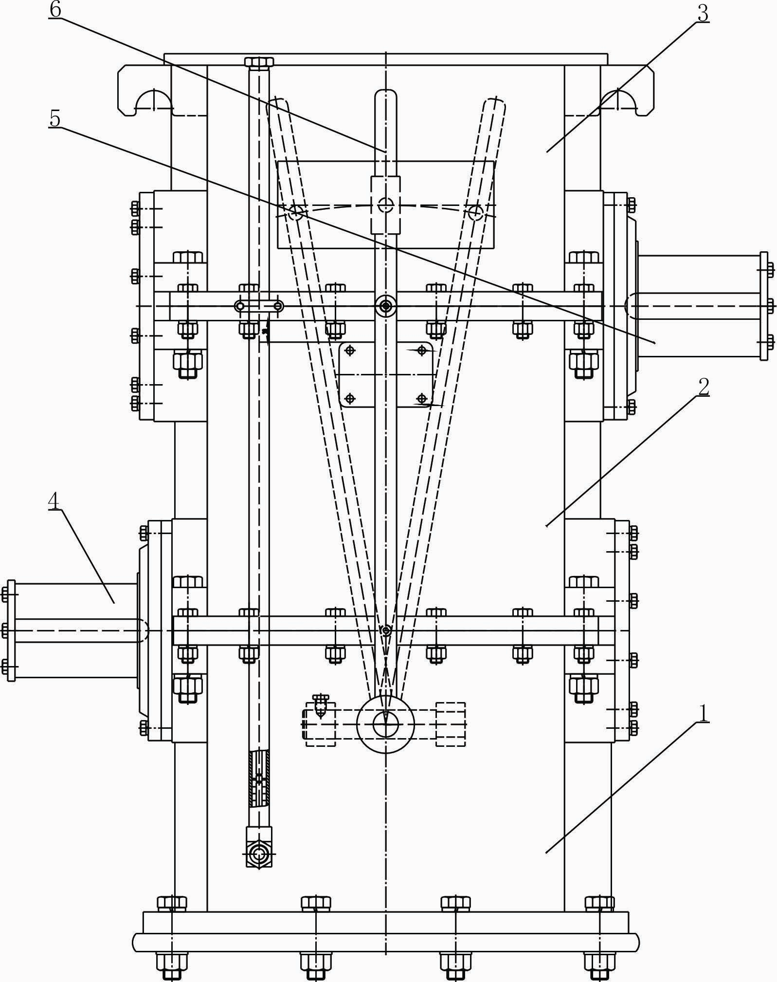
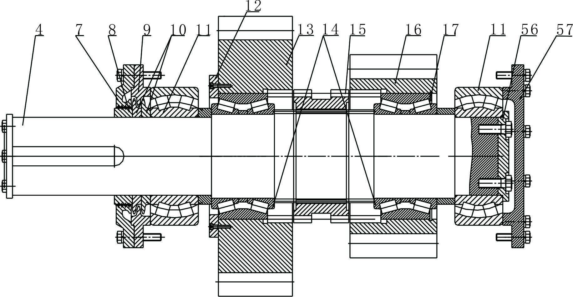
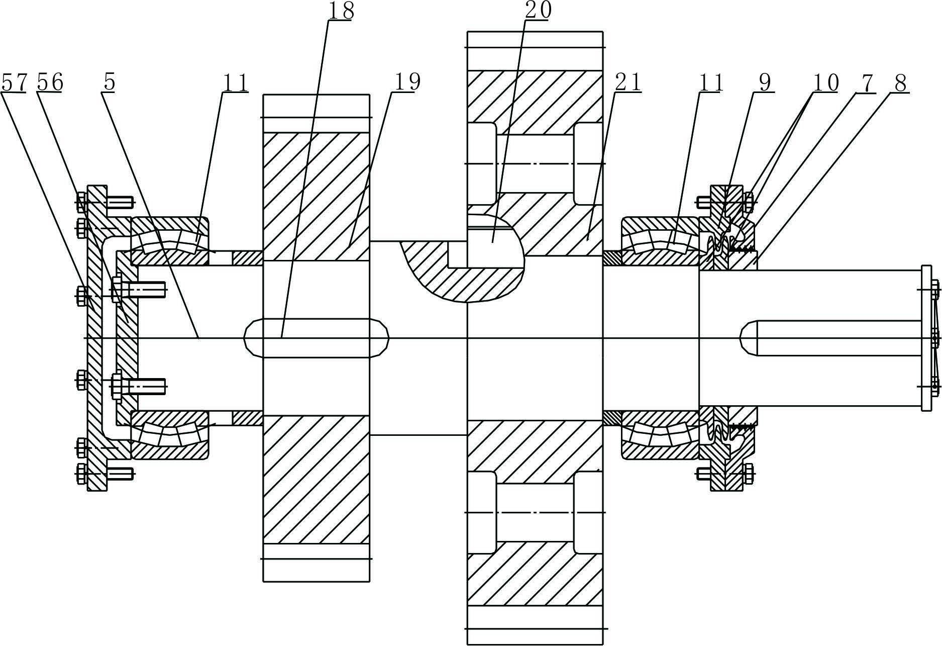
[0048] Such as figure 1 , Figure 7 and Figure 8 As shown, the large-scale oil drilling rig manually shifted drum gear clutch speed reducer provided by the present invention includes a case body assembled vertically from bottom to top by a lower case 1, a middle case 2 and an upper case 3 and The input shaft system, output shaft system, shift control mechanism, lubrication system, breather system and oil measuring rod system arranged in the box; the input shaft system is used for input power and high speed speed; the output shaft system is used for output torque and low speed Rotational speed; the shifting mechanism is used to change the transmission ratio of the input shafting and output shafting. An oil plug b46 is provided in the middle of the bottom of the lower box 1; integral lugs 54 are provided on both sides of the upper end of the...
PUM
Property
Measurement
Unit
length
aaaaa
aaaaa
width
aaaaa
aaaaa
height
aaaaa
aaaaa
Abstract
The invention discloses a manual-shift speed reducer of a crowned-gear clutch for large-size petroleum drilling machines, which comprises a case, an input shaft system, an output shaft system, a shift operating mechanism, a lubricating system, a ventilator system and a measuring rod system. A lower case, a middle case and an upper case are assembled from bottom to top vertically to form the case, the input shaft system, the output shaft system, the shift operating mechanism, the lubricating system, the ventilator system and the measuring rod system are arranged in the case, the input shaft system is used for inputting power and realizing high revolution speed, the output shaft system is used for outputting torque and realizing low revolution speed, and the shift operating mechanism is used for changing the transmission ratio of the input shaft system to the output shaft system. The manual-shift speed reducer of the crowned-gear clutch for the large-size petroleum drilling machines has wide applicable range of environmental temperature, is capable of running on open sites full time, is wide in applicable range of environmental temperature and has the advantages of high bearing capacity, long service life, large output torque, high transmission efficiency, low operation noise and vibration of the case, fine tightness, high exchangeability, convenience in installation, flexibility and stability in shift.
Description
technical field [0001] The invention relates to the technical field of reducers, in particular to a manual gear shifting drum gear clutch reducer for driving a turntable of a large oil drilling rig. Background technique [0002] The rotary table drive of oil drilling rigs is used for manual gear shift drum tooth clutch reducer to realize the rotation of the driven rotary table. When the screw drilling tool is drilling, bear the reaction moment on the drill string; (3) bear the weight of the pipe string when tripping or running the casing, and unload the drill pipe buckle when tripping the drill pipe: (4) adjust and control when drilling directional wells The azimuth of the downhole drill bit. [0003] Due to the low power transmission, low reliability, high noise and high vibration and low efficiency, the traditional reducer for rotary table drive of oil drilling rig cannot meet the requirements of high-performance rotary table drive reducer for oil drilling and production ...
Claims
Application Information
Patent Timeline
Application Date:The date an application was filed.
Publication Date:The date a patent or application was officially published.
First Publication Date:The earliest publication date of a patent with the same application number.
Issue Date:Publication date of the patent grant document.
PCT Entry Date:The Entry date of PCT National Phase.
Estimated Expiry Date:The statutory expiry date of a patent right according to the Patent Law, and it is the longest term of protection that the patent right can achieve without the termination of the patent right due to other reasons(Term extension factor has been taken into account ).
Invalid Date:Actual expiry date is based on effective date or publication date of legal transaction data of invalid patent.