Underwater scanning measurement device and measurement method thereof
A technology of scanning device and measuring device, applied in the direction of measuring device, measuring vibration, vibration measurement in fluid, etc., can solve the problems of low test accuracy, inability to flexibly formulate measurement plan, etc., and achieve good sound permeability, flexible measurement plan, The effect of high positioning accuracy
- Summary
- Abstract
- Description
- Claims
- Application Information
AI Technical Summary
Problems solved by technology
Method used
Image
Examples
Embodiment 1
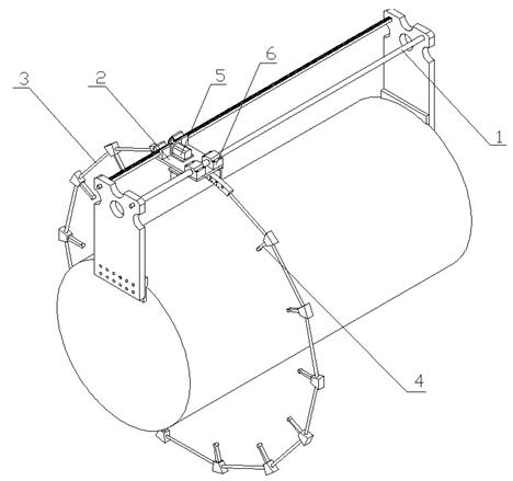
[0026] Such as figure 1 As shown, this embodiment includes a scanning device and an electronic control device connected to the scanning device, and the electronic control device includes a computer and a motion controller connected to the computer, such as figure 2 As shown, the scanning device includes a mounting frame 1, a scanning frame 3 and a servo transmission mechanism 2, the scanning frame and the mounting frame are slidingly connected through the servo transmission mechanism, and a hydrophone 4 is installed on the scanning frame. CAN bus or wireless connection is adopted between the servo transmission mechanism of the scanning device and the motion controller of the electric control device, and between the motion controller and the computer.
[0027] The servo transmission mechanism in this embodiment is composed of a motor 5 and a slider 6 fixedly connected with the scanning frame. Driven by the motor, the slider slides along the mounting frame, and then drives the ...
Embodiment 2
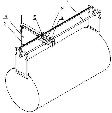
[0037] Such as image 3 As shown, the difference between this embodiment and Embodiment 1 is that the scanning frame 3 adopts a vertical scanning frame, which is composed of a cantilever, a carbon fiber rod with a diameter of 16 mm and an aluminum alloy joint connecting the two, and the carbon fiber rod uses a positioning pin It is connected and fixed at the end of the cantilever by screwing. Considering that the strength of the joint directly affects the accuracy of the final scan, the joint is made of high-strength aluminum alloy instead of non-metallic materials. The distance between the hydrophones is 200mm, and the distance between the hydrophones and the cut plane of the arc vertex on the side of the cabin is 200mm. The vertical scanning frame is installed on the slider in a cantilever manner, and the driving force of the motor is first transmitted to the timing belt through the gear, and then transmitted to the cantilever end gear by the timing belt. The movement in th...
Embodiment 3
[0039] This embodiment includes a scanning device and an electronic control device connected to the scanning device, the electronic control device includes a computer and a motion controller connected to the computer, and the scanning device includes a mounting frame 1, a scanning frame 3 and a servo transmission mechanism 2. The scanning frame is slidably connected to the mounting frame through a servo transmission mechanism, and the hydrophone 4 is installed on the scanning frame. CAN bus or wireless connection is adopted between the servo transmission mechanism of the scanning device and the motion controller of the electric control device, and between the motion controller and the computer.
[0040] Such as Figure 4 As shown, the installation frame of this embodiment is made up of two parallel guide rails, and the guide rails are installed on two guardrails of the submarine, and guide rail spacers are arranged at intervals on the guardrails. Adjust it to a plane, and the...
PUM
 Abstract
Description
Claims
Application Information
 - R&D
- Intellectual Property
- Life Sciences
- Materials
- Tech Scout
- Unparalleled Data Quality
- Higher Quality Content
- 60% Fewer Hallucinations
Browse by: Latest US Patents, China's latest patents, Technical Efficacy Thesaurus, Application Domain, Technology Topic, Popular Technical Reports.
© 2025 PatSnap. All rights reserved.Legal|Privacy policy|Modern Slavery Act Transparency Statement|Sitemap|About US| Contact US: help@patsnap.com


