
Infrared laser measurement image surface alignment device

An infrared laser and alignment device technology, applied in the direction of measuring devices, optical devices, optical radiation measurement, etc., can solve the problems of camera damage, cumbersome and time-consuming operation, and affect camera performance, etc., to achieve the effect of precise alignment

Inactive Publication Date: 2012-07-18
CHANGCHUN UNIV OF SCI & TECH
View PDF0 Cites 17 Cited by
  • Summary
  • Abstract
  • Description
  • Claims
  • Application Information

AI Technical Summary

Problems solved by technology

In order to meet the above requirements, each laser parameter test needs to adjust the optical path and image center alignment of the laser to be tested. Affect the performance of the camera or even cause damage to the camera

Method used


Image

  • Infrared laser measurement image surface alignment device
  • Infrared laser measurement image surface alignment device

Examples


Embodiment Construction

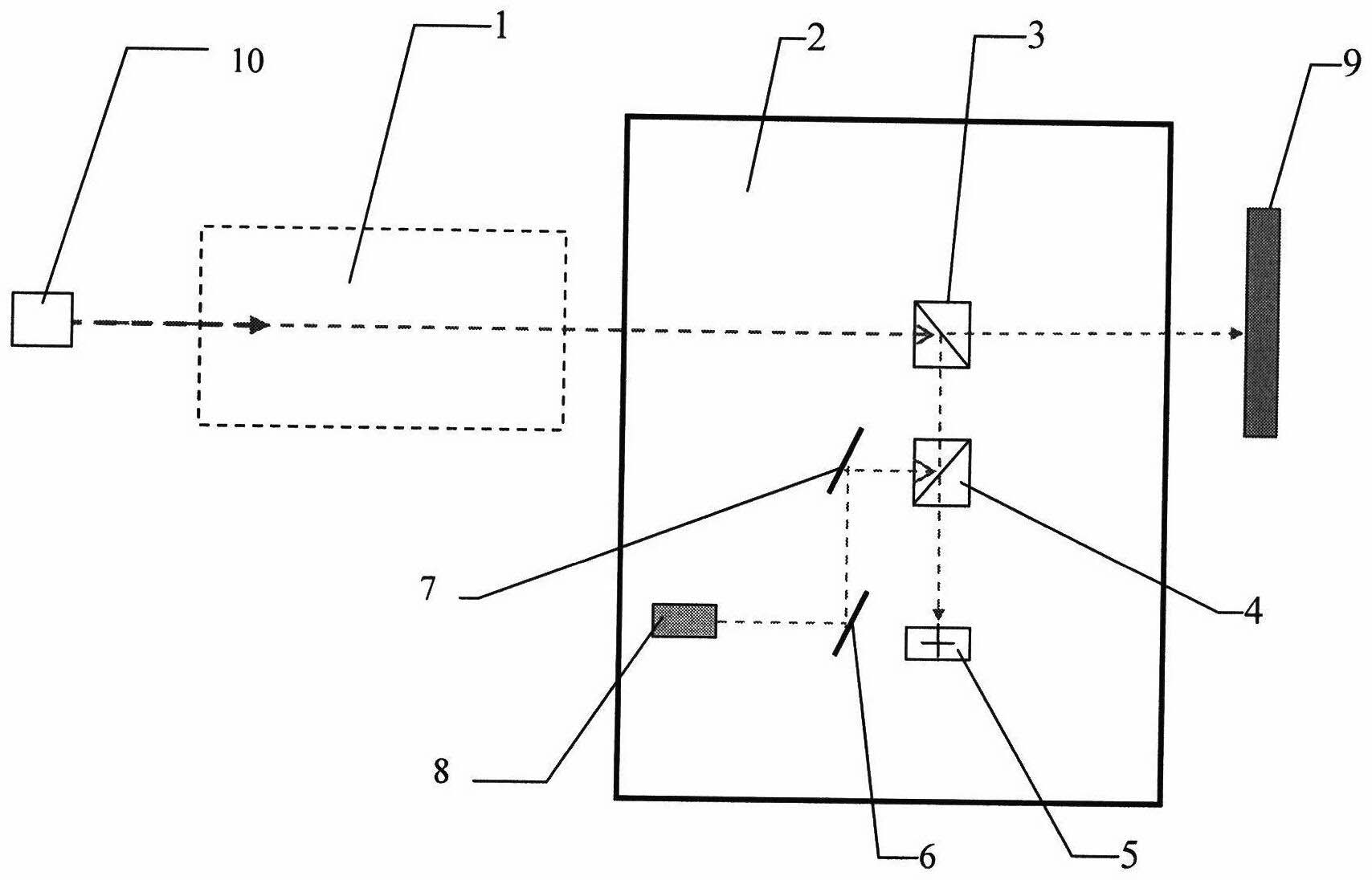
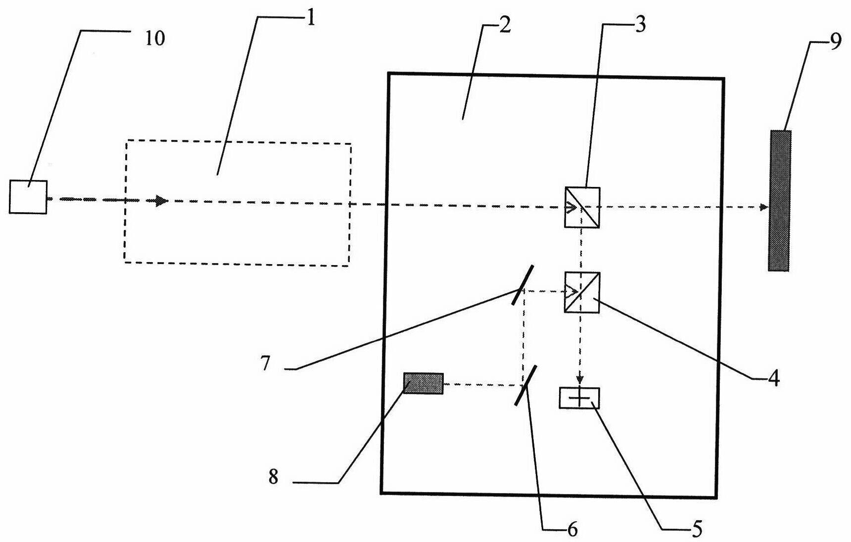
[0012] An infrared laser measurement image alignment device, such as figure 1 As shown, the device is composed of a measured laser 10, an indicating laser 8, a first reflector 6, a second reflector 7, a first dichroic prism 3, a second dichroic prism 4 and an alignment reticle 5; The measuring laser 10 is placed on the four-dimensional optical adjustment frame, which can be adjusted in height, level, pitch and azimuth; the indicating laser 8 is a green laser with a wavelength of 532nm; the first reflector 6 and the second reflector 7 are 2.54cm in diameter The plane reflectors are respectively placed on the two-dimensional optical adjustment frame, which can be adjusted in pitch and azimuth; the first beam splitting prism 3 and the second beam splitting prism 4 are right-angle beam splitting prisms which are respectively glued together by two triangular prisms, and the first beam splitting prism The beam-splitting prism 3 is used to split the incident laser light from the meas...


PUM


Abstract

The invention relates to an infrared laser measurement image surface alignment device and belongs to the technical field of photoelectric measurement. The device consists of an indication system and an alignment system, wherein the indication system indicates a laser to emit indicating laser; the indicating layer is output after passing through a reflector and a beam splitter prism to indicate laser for the position of an emergent light shaft and the image surface center; the laser to be tested is transmitted to a measurement system through the indicating direction of the indicating laser; an alignment reticle of an alignment system indicates the position of the emergent laser and indicates the laser to be tested to align at the image surface and can convert the invisible infrared laser into visible indicating light; and the laser to be tested aligns at the reticle center of the reticle so as to align at the image surface center. Through the adoption of the device, the laser to be tested can be aligned with the system optical axis and the image surface center quickly and accurately.

Description

technical field [0001] The invention relates to an image plane alignment device for infrared laser measurement, which belongs to the technical field of photoelectric measurement. Background technique [0002] Since the appearance of laser, it has been widely concerned by researchers because of its high brightness, good monochromaticity, strong directionality and other related characteristics. With the continuous development of laser technology, laser has been more and more used in various fields of people's production and life and military warfare. In various applications, it is necessary to test various parameters of the laser beam, especially in the military field, the accurate measurement of the quality of the laser beam is very important for the evaluation of the performance of the laser. Among the currently used laser beam quality testing methods, many laser beam parameters (such as beam divergence) are measured using the photoelectric method, that is, after the laser ...

Claims


Application Information

Patent Timeline
Patent Type & Authority Applications(China)
IPC IPC(8): G01J1/04G01B11/26
Inventor 刘爱伟姜会林韩文波王菲韩福利杨进华
Owner CHANGCHUN UNIV OF SCI & TECH
Features
  • Generate Ideas
  • Intellectual Property
  • Life Sciences
  • Materials
  • Tech Scout
  • Unparalleled Data Quality
  • Higher Quality Content
  • 60% Fewer Hallucinations
Learn More