
Calculation method for detection limit in gas-leakage infrared imaging

A technology of gas leakage and detection limit, which is applied in the direction of radiation pyrometry, by detecting the appearance of fluid at the leakage point, and using liquid/vacuum degree for liquid tightness measurement, etc., can solve the inconvenience and inability to evaluate the design performance of gas imaging system Realize the quantitative detection of gas concentration, the inability to realize the detection of trace gas concentration and other problems, and achieve the effect of simple calculation process and convenient design

Inactive Publication Date: 2012-07-18
BEIJING INSTITUTE OF TECHNOLOGYGY
View PDF0 Cites 10 Cited by
  • Summary
  • Abstract
  • Description
  • Claims
  • Application Information

AI Technical Summary

Problems solved by technology

[0005] Although gas leakage infrared imaging technology has many advantages such as portability, rapidity, and large-scale telemetry, the current passive gas leakage infrared imaging technology is a fast qualitative detection technology based on human eye observation, which cannot achieve quantitative trace gas concentration detection.
When the gas leakage flow rate is very small, the gas cloud concentration is very low, so that I 0 and I 1 If the difference is small, the gas cloud cannot be imaged. Since the passive gas leakage infrared imaging technology cannot realize the quantitative detection of gas concentration, it will bring inconvenience to the design of the gas imaging system and the performance evaluation of the system.

Method used


Image

  • Calculation method for detection limit in gas-leakage infrared imaging
  • Calculation method for detection limit in gas-leakage infrared imaging
  • Calculation method for detection limit in gas-leakage infrared imaging

Examples


Embodiment Construction

[0026] The present invention will be described in detail below in conjunction with the accompanying drawings.

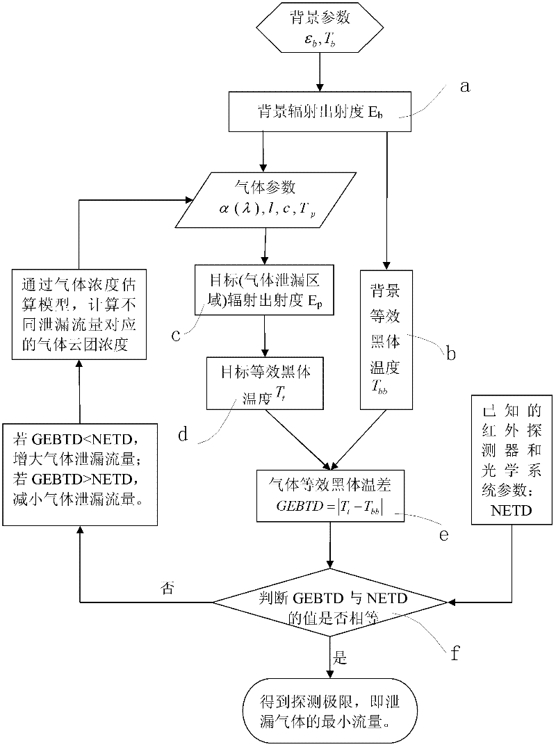
[0027] The specific implementation process in this embodiment includes such as figure 1 The six steps shown:

[0028] Step a. Calculate the imaging detection background radiation emission E b .

[0029] When a gas leak occurs, the area where the gas concentration becomes so thin that it cannot be imaged due to diffusion and the area where the gas cannot diffuse but is still in the field of view is called a gas-free area, and is called the background of imaging detection. Then the imaging detection background radiation emission degree E bIt is equal to the radiation output degree of the background in the field of view when there is no gas leakage, and the background radiation emission degree after atmospheric attenuation is expressed as

[0030] E b = ∫ λ 0 ...


PUM


Abstract

The invention relates to a calculation method for detection limit in gas-leakage infrared imaging, and belongs to the field of gas leakage detection. The calculation method comprises the following steps of: firstly calculating the background radiant exitance when no gas leaks, and taking the background radiant exitance as background radiant exitance for imaging detection; calculating equivalent blackbody temperature of the imaging detection background by the background radiant exitance for imaging detection; secondly, when gas leaks, calculating the radiant exitance after the background radiation is absorbed by gas according to a gas parameter in the background radiant exitance for imaging detection, namely a target radiant exitance for imaging detection; calculating target equivalent blackbody temperature for imaging detection by the target radiant exitance for imaging detection; then calculating an absolute value of the difference between the imaging detection background and the target equivalent blackbody temperature, and defining the absolute value as a gas equivalent blackbody temperature difference; and finally comparing gas equivalent temperature difference with a noise equivalent temperature difference of comprehensive performance parameters of an infrared detector and an optical system, and determining gas-leakage detection limit value, namely, a minimum flow of leaked gas.

Description

technical field [0001] The invention relates to a calculation method for gas leakage infrared imaging detection limit, which belongs to the field of gas leakage detection. Background technique [0002] According to the statistics of my country's tank container / tank truck transportation industry, so far, my country has transported more than 130 kinds of hazardous chemicals, among which the transportation of toxic, harmful, flammable and explosive gases is the top priority. For example, in addition to liquefied petroleum gas, my country's annual output of chlorine alone has exceeded 6 million tons, and 0.1 mg of chlorine per cubic meter of air is enough to cause harm to the environment and personnel. According to the national "Chlorine Gas Safety Regulations GB 11984-89", the workshop (workplace) that produces and uses chlorine gas, the maximum allowable concentration of chlorine gas in the air is 1mg / m 3 . During the transportation of hazardous chemicals, the leakage of tox...

Claims


Application Information

Patent Timeline
IPC IPC(8): G01M3/04G01J5/00
Inventor 王岭雪龙云婷李家琨王美荣高岳
Owner BEIJING INSTITUTE OF TECHNOLOGYGY
Learn More