Method and device for testing speed of servo motor during low-speed running

A low-speed operation, servo motor technology, used in measuring devices, low-speed motor control, linear/angular velocity measurement, etc., can solve the problem of lack of motor speed information processing, inability to intuitively and easily analyze low-speed operation performance of servo motors, and inability to independently test objects, etc. problems to facilitate analysis and judgment

Inactive Publication Date: 2012-07-18
ESTUN AUTOMATION TECH +1
View PDF3 Cites 16 Cited by
  • Summary
  • Abstract
  • Description
  • Claims
  • Application Information

AI Technical Summary

Problems solved by technology

[0004] The existing motor speed measuring device has the following disadvantages when measuring the low-speed performance of the servo: it cannot be independent of the test object;

Method used


Image

  • Method and device for testing speed of servo motor during low-speed running
  • Method and device for testing speed of servo motor during low-speed running
  • Method and device for testing speed of servo motor during low-speed running

Examples


Embodiment 1

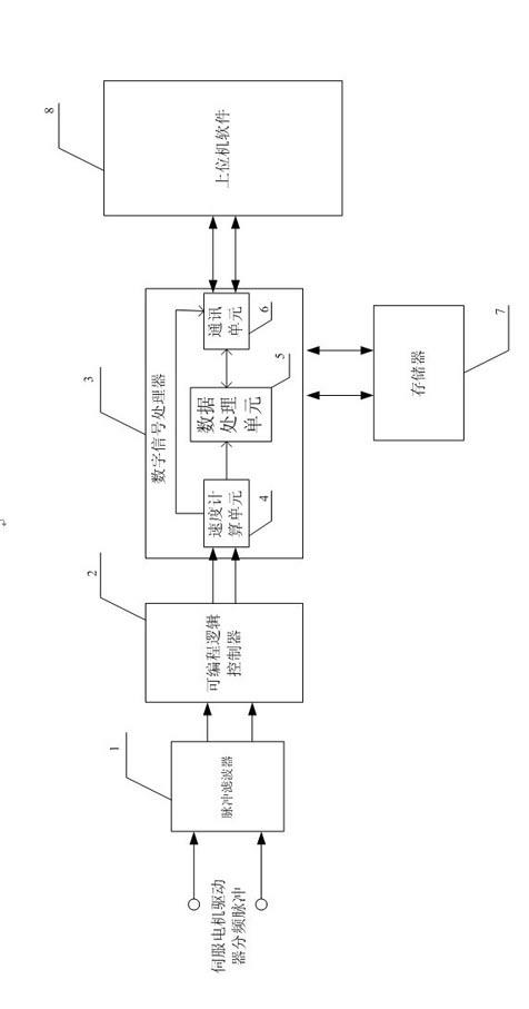
[0032] Such as figure 1 The speed measuring device shown when the servo motor is running at low speed includes a filter 1 for filtering input pulses, a programmable logic controller 2 for counting pulses and time for filtered pulses; a memory 7 for storing speed data; A digital signal processor 3 that uses the frequency cycle method to calculate and process the speed and communicates with the host computer; a host computer software that operates the speed measuring device and displays the speed data. The input terminal of filter 1 is connected to the PG frequency division pulse output of the servo driver; the output of filter 1 is connected to the input terminal of programmable logic controller 2; the programmable logic controller 2 and the digital signal processor 3 pass the data bus and address Bus connection; digital signal processor 3 and memory 7 multiplex data bus and address bus to exchange data; host computer software 8 and digital signal processor 3 are connected thro...

Embodiment 2

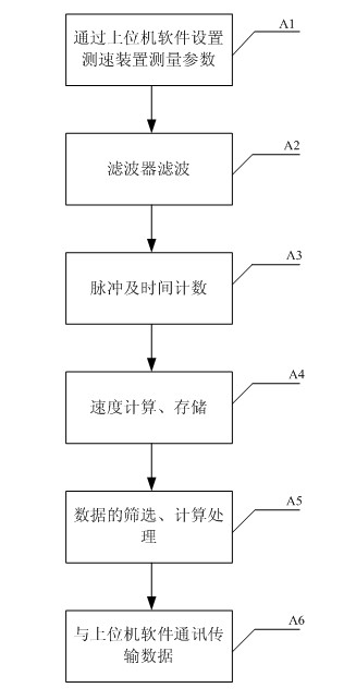
[0035] Such as figure 2 As shown, using the speed measuring device described in Embodiment 1 when the servo motor is running at low speed, the speed measuring steps for measuring the motor speed when the servo motor is running at low speed are as follows:

[0036] Step A1: The upper computer software sets the following parameters through serial port communication: data transmission rate, verification method, sampling times of each group of data, sampling interval time, number of sampling data groups, number of pulses per revolution of the motor, speed measurement resolution; sending speed measurement start instruction.

[0037] Step A2: The pulse filter performs Schmidt shaping on the PG frequency-divided quadrature pulse of the servo driver. After shaping, low-pass filtering is used to filter out high-frequency signals, and then Schmidt shaping is performed on the filtered quadrature pulse.

[0038] Step A3: The programmable logic controller performs frequency multiplicatio...


PUM


Abstract

The invention discloses a method and a device for testing the speed of a servo motor during low-speed running. The device for testing the speed of the servo motor during low-speed running comprises a pulsed filter, a programmable logic controller, a digital signal processor and a storage. The method for testing the speed of the servo motor during low-speed running comprises the following steps of: setting parameters of the device by using upper computer software, performing frequency or period method (M/T method) speed testing on a pulse generator (PG) fractional frequency pulse of a servo driver by using a testing device, and processing multiple batches of data, and after data is screened, displaying by using the upper computer software for analysis. By using the method and the device, the low speed of the motor can be detected independently and accurately; and through visual display of an upper computer, the low-speed running condition of the motor can be analyzed conveniently, and the device for testing the speed of the servo motor can be used as a third-party testing device to meet the servo low-speed performance test requirements.

Description

technical field [0001] The invention relates to a speed measurement method and a speed measurement device of a servo motor, in particular to a speed measurement method and a device for a servo motor running at a low speed. [0002] Background technique [0003] The low-speed operation of the servo motor is one of the performance indicators of the servo drive, and the speed data of the motor at low speed is important information to measure the performance of the servo drive. At low speed, the speed fluctuation of the servo motor is large, and the noise signal is relatively large in proportion to the effective information; the current speed measuring device obtains the speed data of the motor by detecting the encoder pulse signal installed on the motor shaft. This method is not independent of the servo motor. It is easy to cause interference to the test object, or be interfered by the test object; and the current test device does not process the low-speed data of the servo mo...

Claims


Application Information

Patent Timeline
IPC IPC(8): G01P3/481
CPCH02P6/142G01P3/481H02P6/17H02P23/03
Inventor 吴蔚齐丹丹李军良
Owner ESTUN AUTOMATION TECH
Why Eureka
Try Eureka