
Redundancy time difference positioning method and redundancy time difference positioning system

A technology for time-difference positioning and redundant objects, which is used in positioning, radio wave measurement systems, measurement devices, etc., can solve the problems of difficulty in finding and removing redundant objects, positioning of inactive redundant objects, and missed detection of moving redundant objects, and achieves reduction of objective restrictions. , high accuracy, the effect of reducing analysis time

Active Publication Date: 2013-10-16
CASIC DEFENSE TECH RES & TEST CENT
View PDF3 Cites 0 Cited by
  • Summary
  • Abstract
  • Description
  • Claims
  • Application Information

AI Technical Summary

Problems solved by technology

However, this method is greatly affected by human vision, hearing and the external environment, and can only detect relatively large mobile redundant objects, with low sensitivity and high missed detection of mobile redundant objects, and cannot accurately locate mobile redundant objects.
In the prior art, there is also a regional positioning method using multiple transducers. This method is simple and intuitive, but the positioning is rough and it is difficult to find and remove redundant objects.

Method used

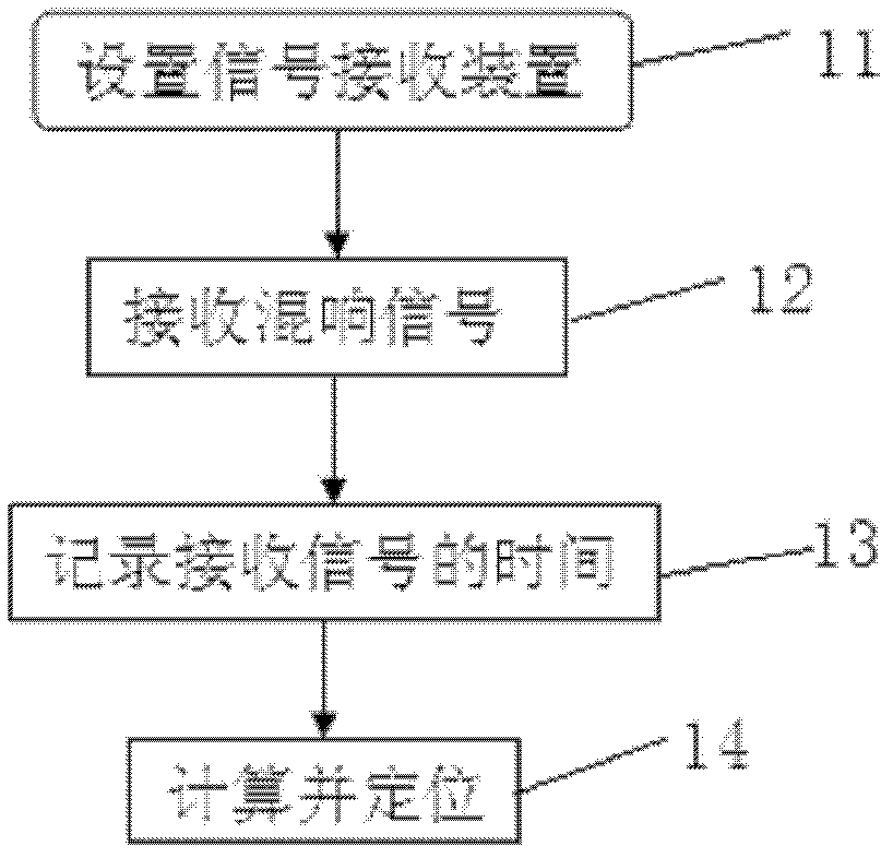
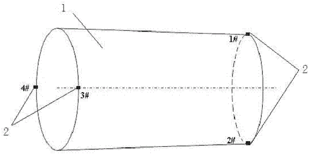
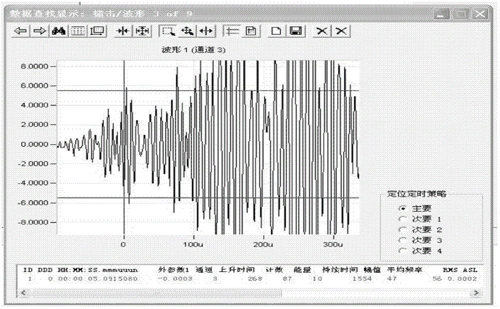

Image

  • Redundancy time difference positioning method and redundancy time difference positioning system
  • Redundancy time difference positioning method and redundancy time difference positioning system
  • Redundancy time difference positioning method and redundancy time difference positioning system

Examples


Embodiment Construction

[0019] In order to make the object, technical solution and advantages of the present invention clearer, the present invention will be described in further detail below in conjunction with specific embodiments and with reference to the accompanying drawings.

[0020] There will be two processes when the mobile excess is displaced in the cabin: the sliding process and the impact process. This process is a random combination process of the sliding process and the impact process. During the sliding and impacting of the cabin wall, elastic stress waves and acoustic reverberation signals will be propagated in the cabin shell material. Piezoelectric transducers are used to pick up reverberation signals, and the signal source can be located by measuring the time difference of receiving signals of different piezoelectric transducers, combined with the sound velocity of the cabin and the spacing and geometric distribution of piezoelectric transducers.

[0021] With the measurement metho...


PUM


Abstract

The invention discloses a redundancy time difference positioning method and a redundancy time difference positioning system. Piezoelectric transducers are fixedly arranged on a truncated-cone-shaped cabin section in advance for receiving redundancy signals, and a signal processing device determines signal source positions of the redundancy signals in the time difference positioning method. The redundancy time difference positioning method and the redundancy time difference positioning system can help detectors to determine specific positions of redundancy in the cabin section, facilitate removing of moving redundancy, and can help the detectors to distinguish signals of some moving parts in the cabin section and reduce analyzing time of moving redundancy signals.

Description

technical field [0001] The invention relates to the field of non-destructive testing, in particular to a positioning method and a system thereof. Background technique [0002] Aerospace systems have high requirements for product reliability, and strictly prevent and control redundant products inside the product. For small devices such as electronic circuits, components, and relays, particle impact noise detection (PIND) is used to detect redundant objects, and the detection sensitivity is high. However, this method uses a single piezoelectric transducer for detection, and the power of the vibration excitation device is low, so it can only detect Small products with a mass of no more than 500g, and the detection of excess in large products can only be detected in sections and regions. For the bomb-on instrument, the piezoelectric transducer is used to collect the mobile excess signal under shaking conditions, and the displacement signal of the active excess is identified acc...

Claims


Application Information

Patent Timeline
Patent Type & Authority Patents(China)
IPC IPC(8): G01S5/06
Inventor 杨京赵长兴沈枫任毅黄小贝
Owner CASIC DEFENSE TECH RES & TEST CENT
Learn More