
Method for erasing single-transistor memory array

A technology of memory array and target memory, which is applied in the field of single-tube memory array erasing, and can solve problems such as increased reliability failure risk, raised threshold voltage, lack of monitoring and adjustment means, etc.

Active Publication Date: 2015-04-08
SHANGHAI HUAHONG GRACE SEMICON MFG CORP
View PDF2 Cites 0 Cited by
  • Summary
  • Abstract
  • Description
  • Claims
  • Application Information

AI Technical Summary

Problems solved by technology

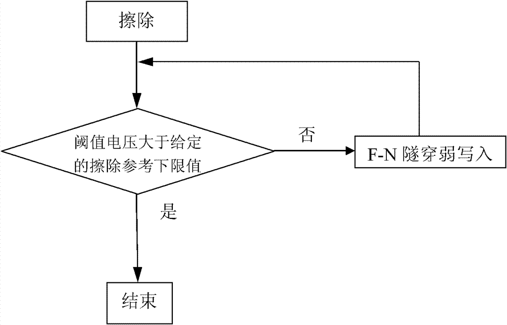
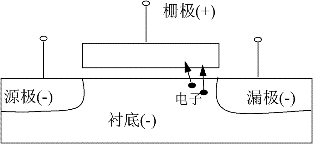
When the F-N tunneling effect is weakly written to the over-erased memory cell, under the action of the positive electric field from the gate to the substrate, the same as the over-erased memory cell with a low threshold voltage, the threshold voltage is normal or even high The normally erased memory cells are also affected by the substrate-gate injected electron current, such as image 3 , Figure 4 As shown, after electrons are injected from the substrate into the charge-trapping layer, the threshold voltage is raised monotonously, causing the erasing window of some memory cells in the single-transistor memory array to be too low, such as Figure 5 shown
These memory cells with too low erasing window may not have enough erasing window to meet the requirements of data retention reliability, and the process of F-N tunneling effect on the over-erased memory cells is to erase them all The threshold voltage of the target memory cell is greater than the given erase reference lower limit value, and the target memory cell with a smaller erase window (higher threshold voltage) lacks effective monitoring and adjustment means, which increases due to the erasure window Risk of reliability failure due to too small

Method used


Image

  • Method for erasing single-transistor memory array
  • Method for erasing single-transistor memory array
  • Method for erasing single-transistor memory array

Examples


Embodiment Construction

[0029] One embodiment of the method for erasing a single-pipe memory array of the present invention is as follows: Figure 6 shown, including the following steps:

[0030] 1. Erase each target memory cell;

[0031] 2. Read the threshold voltage of each target memory cell, compare the current threshold voltage of each target memory cell with the same threshold voltage upper limit, if the current threshold voltage of a target memory cell is greater than the threshold voltage upper limit value, proceed to step 1, otherwise proceed to step 3;

[0032] 3. Ground the substrate and the source of each target memory cell, and connect the gate and the drain to the pulse voltage respectively;

[0033] Four. The current threshold voltage of each target memory unit is compared with the same threshold voltage lower limit value respectively, if the current threshold voltage of each target memory unit is greater than the threshold voltage lower limit value, then carry out step 7, otherwise ...


PUM


Abstract

The invention discloses a method for erasing a single-transistor memory array, which comprises the following steps of: erasing a threshold voltage of each target memory unit to be below an upper limit value of a given threshold voltage, and finally enabling the threshold voltages of all the target memory units of the signal-transistor memory array under the erasing state to be distributed within a give safety window range by utilizing the characteristic that the hot carrier injection property changes along with difference of threshold voltages of the memory units; injecting hot electrons into the over-erased target memory units which have lower threshold voltages, so that the threshold voltages of the over-erased target memory units are increased to be above a lower limit value of the given threshold value for avoiding read interference; and injecting electron holes to the weakly-erased target memory units which have higher threshold voltages into holes, so that the threshold voltages of the weakly-erased target memory units are converged to be below the upper limit value of the given threshold voltage, so that enough erasing windows can be provided for meeting the requirement on data retention reliability.

Description

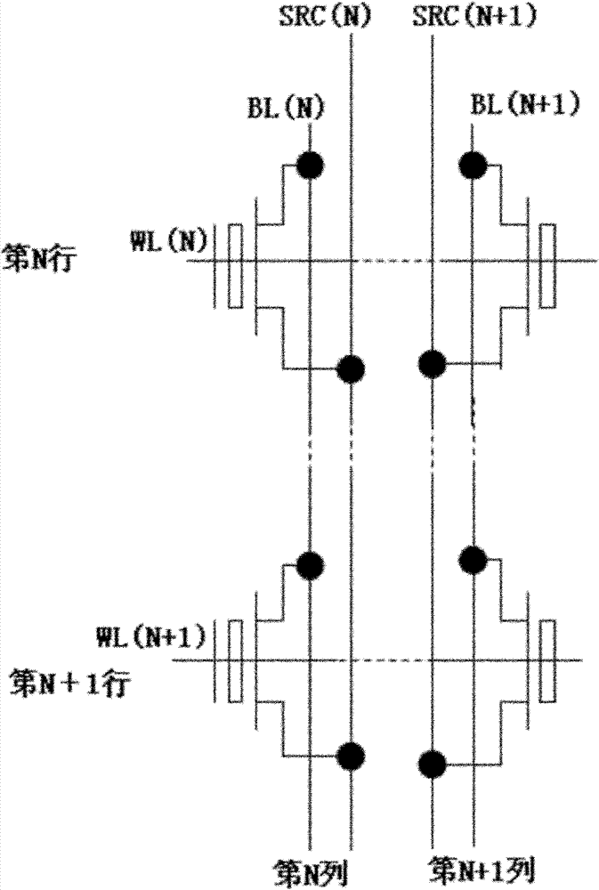
technical field [0001] The invention relates to semiconductor technology, in particular to a method for erasing a single-tube memory array. Background technique [0002] Commonly used non-volatile flash memories include floating gate memories, SONOS (Silicon-Oxide-Nitride-Oxide-Silicon) memories, nanocrystal memories, and the like. The device structure of a non-volatile flash memory cell is similar to that of a common CMOS device. The only difference is that the oxide between the gate and the substrate in the CMOS structure has become a stacked structure of insulating layer-charge trapping layer-insulating layer The purpose of storing information is achieved by injecting or erasing charges into the charge trapping layer in the middle of the stacked structure. [0003] In non-volatile single-transistor memory arrays, such as figure 1 As shown, a column of the memory is formed by parallel connection of multiple storage tubes sharing the source and drain. A single storage tub...

Claims


Application Information

Patent Timeline
Patent Type & Authority Patents(China)
IPC IPC(8): G11C16/14
Inventor 唐立文陈广龙陈昊瑜陈华伦
Owner SHANGHAI HUAHONG GRACE SEMICON MFG CORP
Learn More