
Integrated sealing elastic keyboard pad

A sealing elastic and integrated technology, applied in the direction of electrical components, electric switches, circuits, etc., can solve the problems of resource waste, cumbersome operation, high material cost, etc., achieve the effect of simplifying the manufacturing process, overcoming the large number, and reducing the manufacturing cost

Active Publication Date: 2012-07-18
GSK CNC EQUIP
View PDF5 Cites 5 Cited by
  • Summary
  • Abstract
  • Description
  • Claims
  • Application Information

AI Technical Summary

Problems solved by technology

The traditional replacement method is to dismantle and replace the entire mask structure, which is cumbersome for the situation where only a single function key indicator needs to be replaced, and the replacement of the entire mask structure is likely to cause waste of resources and cost a lot. At the same time, the general operation function of a standard product is also difficult to meet the needs of most machine tools
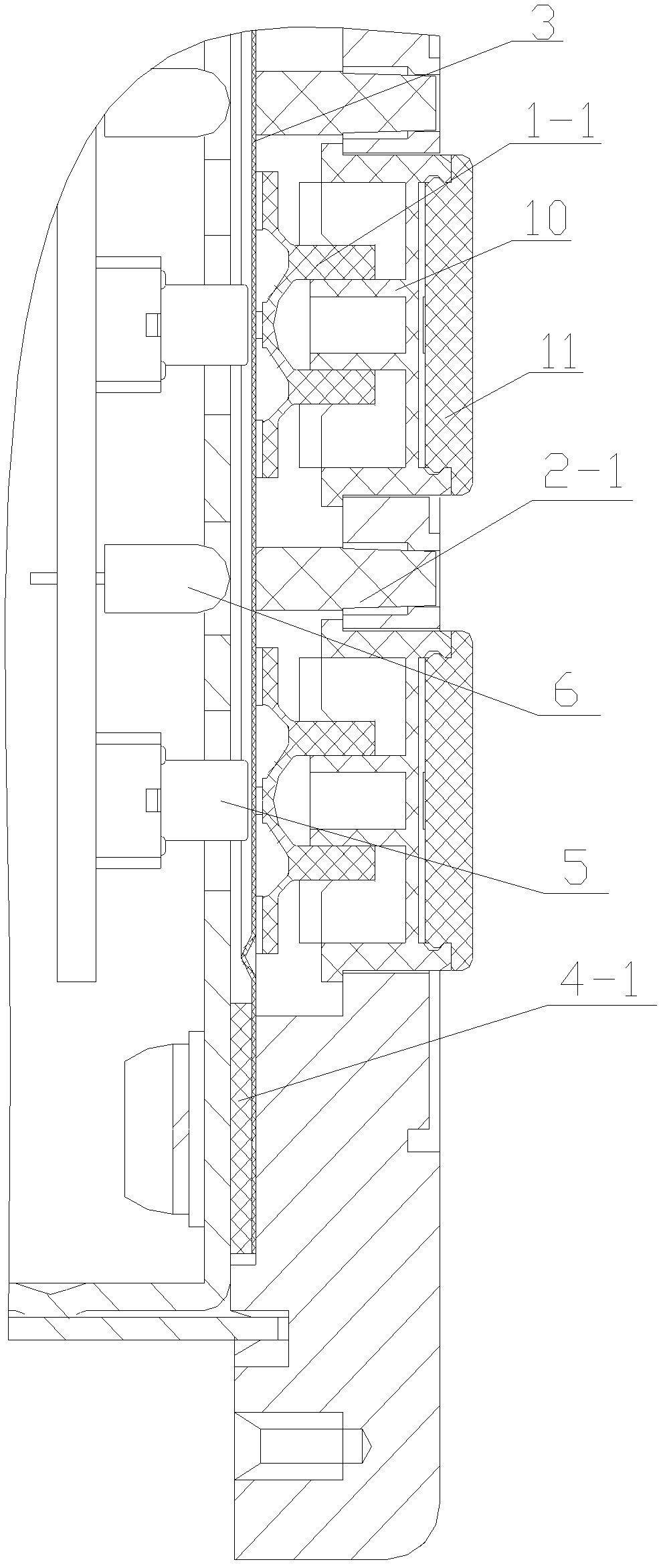
For this reason, the keycap structure of replaceable logo has appeared at present, but this also has new requirements to the structure inside the keyboard, especially the keyboard pad. The current structure is as follows: figure 1 As shown, the keyboard pad is composed of a plurality of key pads 1-1, a plurality of light guide columns 2-1 made of high light transmittance materials, a protective sheet 3 and a sealing pad 4-1. Then fix the keypad and light guide column one by one according to the needs, and set a sealing gasket between the protective sheet and the keyboard. The assembly of the keyboard pad with this structure is very troublesome when used, and the product needs to be produced in multiple times. The manufacturing cost is too high , there is a lot of resistance in product manufacturing; at the same time, the light guide column in this structure is a solid structure. The range of material selection is small, the material cost is high, and the light transmittance of the light guide column cannot be substantially improved

Method used


Image

  • Integrated sealing elastic keyboard pad
  • Integrated sealing elastic keyboard pad
  • Integrated sealing elastic keyboard pad

Examples


Embodiment

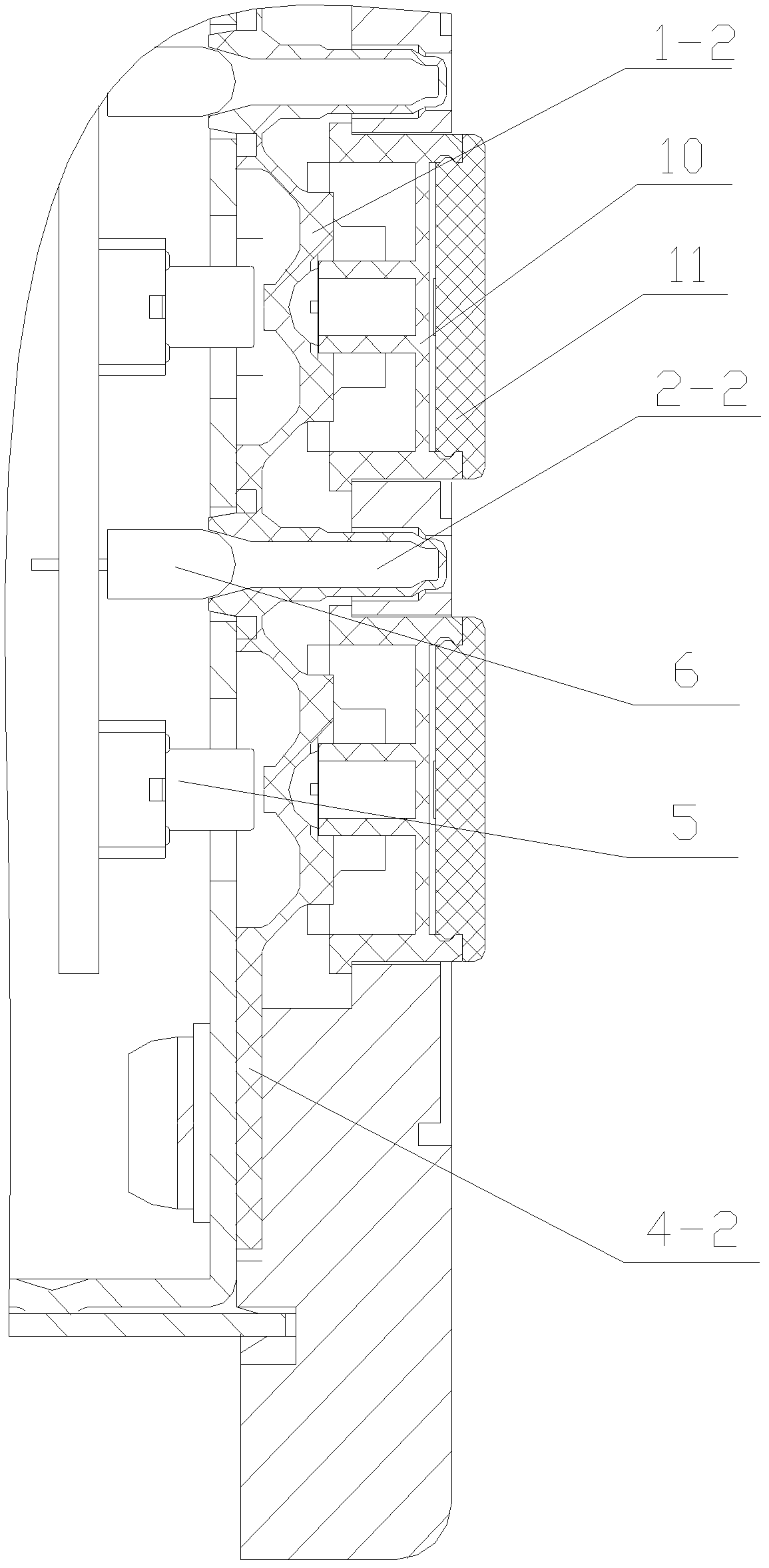
[0026] This embodiment is a kind of one-piece sealed elastic keyboard pad, its structure is as follows: figure 2 As shown, it includes a plurality of keypads 1-2 and a plurality of light guide columns 2-2, and a plurality of keypads and a plurality of light guide columns are combined into an integrated structure. Each keypad is located above the corresponding key 5 on the keyboard, and each light guide column It is located above the corresponding indicator light 6 on the keyboard.

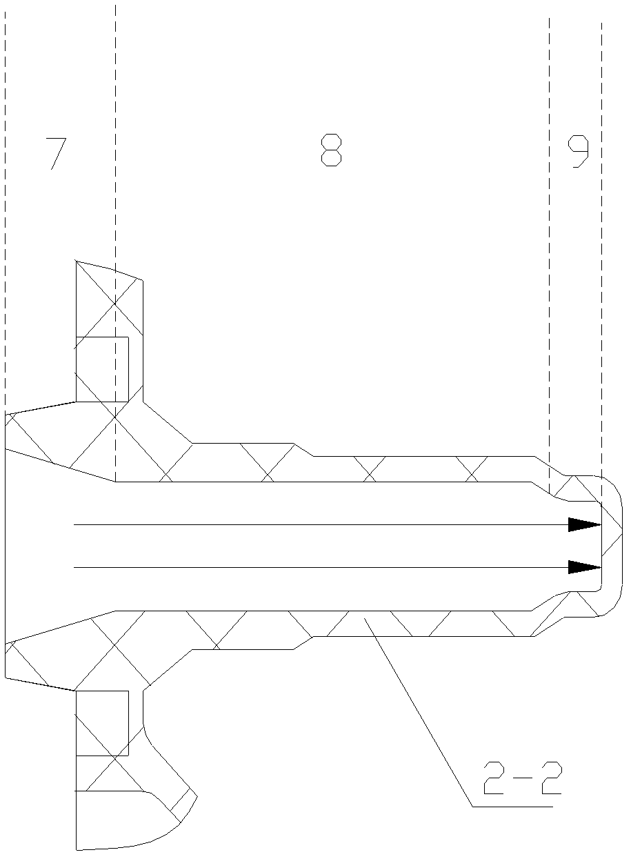
[0027] Among them, the light guide column is a hollow structure, see image 3 or Figure 4 , the end of the light guide column connected to the indicator light is an open end, and the other end of the light guide column is a closed end.

[0028] The end faces of the closed ends are planar.

[0029] The end surface thickness of the closed end of the light guide column is less than or equal to 0.8mm. In the case of ensuring that the closed end of the light guide column will not break due to being...


PUM

PropertyMeasurementUnit
Thicknessaaaaaaaaaa

Abstract

The invention discloses an integrated sealing elastic keyboard pad which comprises a plurality of key pads and a plurality of light guide pillars. A plurality of key pads and a plurality of light guide pillars are combined into an integrated structure; each key pad is positioned on a corresponding key on a keyboard; each light guide pillar is positioned on a corresponding indicating lamp on the keyboard; the light guide pillars are of a hollow structure; the ends of the light guide pillars, which are connected with the indicating lamps, are open ends; and the other ends of the light guide pillars are closed ends. According to the integrated sealing elastic keyboard pad, a plurality of parts are combined into the integrated structure and a protection sheet is saved, so that the materials are saved, the possibility of generating gaps when the parts are matched is also avoided and the integrated sealing elastic keyboard pad has a better sealing effect; in the manufacturing process, the integrated sealing elastic keyboard pad can be formed in one step by adopting a conventional compression molding or injection molding process, so that the manufacturing process of the integrated sealing elastic keyboard pad is simplified and the manufacturing cost is reduced; in the using process, the integrated sealing elastic keyboard pad is used as one part, so that the defects of large number of the parts of a conventional keyboard pad and fussiness for installation are overcome and the integrated sealing elastic keyboard pad is convenient to use; and the light guide pillars are of a hollow structure, so that the light guide rate of the integrated sealing elastic keyboard pad is improved, the material selection range can also be enlarged and the hollow structure of the light guide pillars is beneficial for reducing the production cost.

Description

technical field [0001] The invention relates to the field of keyboards used in electronic products, in particular to an integrated sealed elastic keyboard pad used in a numerical control system of a machine tool. Background technique [0002] With the continuous development of technology, the requirements for machine tool processing technology in all walks of life are also constantly increasing. The CNC system of machine tools has been developed rapidly, and the operating functions of various machine tools are not the same. This requires that the various function definition symbols of the operation panel of the CNC system of machine tools can be Change or set anytime. The traditional replacement method is to dismantle and replace the entire mask structure, which is cumbersome for the case where only a single function key indicator needs to be replaced, and the replacement of the entire mask structure is likely to cause waste of resources and cost a lot. At the same time, th...

Claims


Application Information

Patent Timeline
IPC IPC(8): H01H13/83
Inventor 孙传乐
Owner GSK CNC EQUIP
Learn More