Electric connector sealing structure

A sealing structure and electrical connector technology, applied in the parts, connections, circuits and other directions of the connecting device, can solve the problems of poor sealing at the joint, cracks in the glue-filled sealing layer, and decreased sealing of the connector, and achieve a good sealing degree. , High sealing level, convenient construction effect

Inactive Publication Date: 2012-07-18
SHANGHAI AEROSPACE SCI & IND ELECTRIC APPLIANCE RES INST
View PDF3 Cites 18 Cited by
  • Summary
  • Abstract
  • Description
  • Claims
  • Application Information

AI Technical Summary

Problems solved by technology

The sealing method adopted by the connector in the prior art mainly adopts the method of insert injection molding or sintering between the shell and the contact piece connected by the cable. In the former, the sealant is first poured at the connection between the cable and the connector, and then The casing and the cable are embedded and injected. The above-mentioned embedded injection-molded sealed connector has good pressure resistance under normal conditions, but with the change of ambient temperature, due to the difference in expansion coefficient between the metal casing and the internal embedded injection molding material, resulting in Cracks appear between the metal shell, the cable and the internal embedded injection molding material, resulting in a decrease in the airtightness of the connector; in the latter, a sintered layer is implemented between the contact between the shell and the cable. There are mainly polyether, polyether and glass, glass and ceramics or ceramics. The sealed structure completed by sintering is sufficient to meet the strength requirements of the connector. Bubbles are unavoidable, leading to poor airtightness defects at the joints. Although compensation measures for potting sealants are taken, under complex temperature environments, cracks often appear in the potting sealant layer due to aging, resulting in connectors. Decreased airtightness or air leakage

Method used


Image

  • Electric connector sealing structure
  • Electric connector sealing structure
  • Electric connector sealing structure

Examples


Embodiment Construction

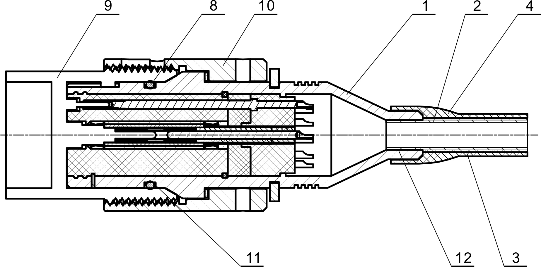
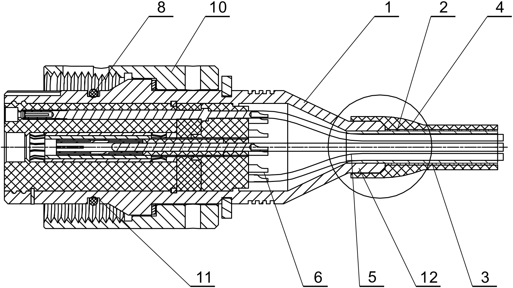
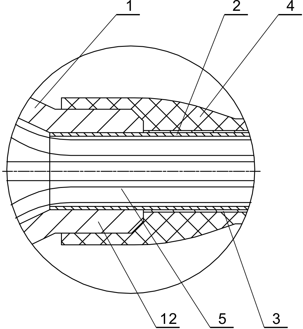
[0010] refer to figure 1 , figure 2 , image 3 , the present invention includes a plug shell 1, a copper tube 2, a heat shrinkable tube 3, a rubber sleeve 4, a sealing ring 8, a socket 9 and a connecting nut 10, the plug shell 1 is provided with a sealing groove 11 and a cable socket 12, The socket 9 is provided with external threads; the copper tube 2 is partially inserted into the cable socket 12 and welded thereto, the heat shrinkable tube 3 is wrapped on the exposed surface of the copper tube 2, and the rubber sleeve 4 is wrapped around the wire of the plug shell 1. The outer surface of the cable socket 12 and the heat shrinkable tube 3, the sealing ring 8 is set in the sealing groove 11 of the plug shell 1, the socket 9 is set on one end of the plug shell 1 and compresses the sealing ring 8, and the connecting nut 10 is set on the other end of the plug shell 1 And engage with the external thread of socket 9.

[0011] The present invention is used like this:

[0012] ...


PUM


Abstract

The invention discloses an electric connector sealing structure, which comprises a plug shell, a copper tube, a shrinkable tube, a rubber sleeve, a sealing ring, a socket and a connecting nut, wherein the copper tube is locally inserted in a cable socket and is welded with the cable socket; the shrinkable tube is coated on an exposed surface of the copper tube; the rubber sleeve is coated on outer surfaces of the plug shell and the shrinkable tube; the sealing ring is arranged in a sealing groove of the plug shell; the socket is sleeved at one end of the plug shell; and the connecting nut is sleeved at the other end of the plug shell and is meshed with external threads of the socket. The invention has the advantages that: the electric connector sealing structure has a simple structure, high sealing degree and high reliability and is convenient to construct; and moreover, the electric connector sealing structure is suitable for a high-temperature high-pressure working environment and a working environment with a wide temperature difference range and is also suitable for a working environment with an explosion-proof requirement, and a high sealing level between the interior of the connector and the outside is guaranteed after the electric connector is connected with a cable.

Description

technical field [0001] The present invention relates to the technical field of electrical connectors and the hermetic connection between cables and connectors, in particular to a sealing structure of electrical connectors. Background technique [0002] Electrical connectors are important components for connecting cables and electrical equipment, especially in the oil and gas industry. For connectors, in addition to meeting conventional performance indicators, the connection structure between cables and connectors must also have explosion-proof, It has the characteristics of high temperature resistance, high pressure resistance and air tightness. The sealing method adopted by the connector in the prior art mainly adopts the method of insert injection molding or sintering between the shell and the contact piece connected by the cable. In the former, the sealant is first poured at the connection between the cable and the connector, and then The casing and the cable are embedde...

Claims


Application Information

Patent Timeline
Patent Type & Authority Applications(China)
IPC IPC(8): H01R13/502H01R13/52
Inventor 宁海波王令红王迎春徐悦
Owner SHANGHAI AEROSPACE SCI & IND ELECTRIC APPLIANCE RES INST
Why Eureka
Try Eureka