Non-contact reversing contactor

A non-contact and contactor technology, applied in the direction of motor generator/starter, single multi-phase induction motor starter, electrical components, etc., can solve the problem of affecting production stability, inability to control thyristors, and increasing product scrap rate, etc. problems, to achieve the effect of avoiding phase-to-phase short-circuit faults, reliable interlock function, and improving control accuracy

Active Publication Date: 2012-07-18
淄博延展电气科技有限公司
View PDF7 Cites 4 Cited by
  • Summary
  • Abstract
  • Description
  • Claims
  • Application Information

AI Technical Summary

Problems solved by technology

[0003] 1. The mechanical contacts of ordinary contactors are difficult to meet the switching frequency requirements, and as the switching frequency increases, its service life is greatly reduced, causing production equipment failures, affecting production continuity and production efficiency, and is extremely easy to improve Product rejection rate
[0004] 2. Due to the high switching frequency, the iron core and contacts of ordinary contactors are accelerated to wear, causing the start-stop time to gradually change, resulting in changes in positioning, and ultimately affecting the stability of production
[0005] 3. In some places where high switching frequency and frequent reversing are required, the failure rate of ordinary contactors is higher, and even cannot be used at all
[0006] Based on the problems and defects of the above ordinary contactors, people have developed a non-contact reversing contactor based on thyristors, which replace the above-mentioned ordinary contactors with thyristors, which solves the problem of common contactors in the process of opening and closing. The problem of sparks, while meeting the switching frequency requirements of modern production, but in practical applications, each thyristor cannot be precisely controlled, resulting in a series of problems such as phase-to-phase short circuit, resulting in non-contact reversing contactors not being used Widely used, mostly still in the common contactor stage

Method used


Image

  • Non-contact reversing contactor
  • Non-contact reversing contactor
  • Non-contact reversing contactor

Examples


Embodiment Construction

[0040] The present invention will be further described in detail below in conjunction with the accompanying drawings and specific embodiments.

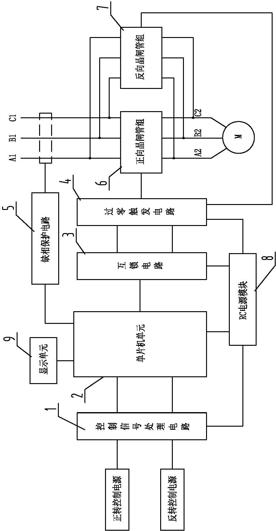
[0041] Such as figure 1 , 4As shown, in the present invention, the three-phase power supply at the input end is respectively marked as A1, B1 and C1, and the three-phase power supply at the output end is respectively marked as A2, B2 and C2, and five thyristor modules capable of controlling the full-wave conduction of alternating current are arranged in total SCR1, SCR2, SCR3, SCR4, and SCR5. Among them, SCR1 is connected to the A1A2 phase line of the three-phase power supply, SCR2 is connected to the B1B2 phase line of the three-phase power supply, SCR3 is connected to the C1C2 phase line of the three-phase power supply, and SCR4 is connected to the A1C2 phase line of the three-phase power supply. SCR5 is connected to the C1A2 phase line of the three-phase power supply. When the thyristor modules SCR1, SCR2, and SCR3 are turned on,...


PUM


Abstract

The invention discloses a non-contact reversing contactor, and belongs to the technical field of motor control. The non-contact reversing contactor comprises three phases of power supplies A1, B1 and C1 at an input end, three phases of power supplies A2, B2 and C2 at an output end, a positive thyristor group and a negative thyristor group, and is characterized by also comprising a singlechip unit and an interlocking module in (a) software or/and hardware form(s), wherein the singlechip unit controls the switching-on/off of the positive and negative thyristor groups through the interlocking module, and makes the positive and negative thyristor groups asynchronously in an on state. According to the non-contact reversing contactor, due to the adoption of the singlechip unit, control accuracy is improved; and the singlechip unit controls the switching-on/off of the positive and negative thyristor groups through the interlocking module, so that interlocked switching-on control over the positive and negative thyristor groups is realized, and a phase fault caused by the simultaneously switching-on of the positive and negative thyristor groups is avoided.

Description

technical field [0001] The invention belongs to the technical field of motor control, and in particular relates to a non-contact reversing contactor. Background technique [0002] With the rapid development of industrialization, the output and production efficiency of industrial products have been greatly improved. The switching frequency and reliability of ordinary contactors can no longer meet the needs of modern production processes. The problems and shortcomings are mainly manifested in the following points: [0003] 1. The mechanical contacts of ordinary contactors are difficult to meet the switching frequency requirements, and as the switching frequency increases, its service life is greatly reduced, causing production equipment failures, affecting production continuity and production efficiency, and is extremely easy to improve Product rejection rate. [0004] 2. Due to the high switching frequency, the iron core and contacts of ordinary contactors are accelerated to...

Claims


Application Information

Patent Timeline
Patent Type & Authority Applications(China)
IPC IPC(8): H02P1/40H02H7/09
Inventor 郭立军李磊王锦泽马素科刘刚陶祥军李国刚许立菊
Owner 淄博延展电气科技有限公司
Why Eureka
Try Eureka