
Self-phase differential interference optical signal receiving device

A signal receiving device and a technology of self-phase difference, which is applied in the field of optical signal demodulation, can solve the problems that are not conducive to reducing the bit error rate of communication signals, the lack of precision adjustment devices and phase-locked loops, and the inability to remove DC components, etc., to meet high The effects of speed communication, maintaining accuracy, and stabilizing optical path difference

Active Publication Date: 2014-10-15
SHANGHAI INST OF OPTICS & FINE MECHANICS CHINESE ACAD OF SCI
View PDF5 Cites 2 Cited by
  • Summary
  • Abstract
  • Description
  • Claims
  • Application Information

AI Technical Summary

Problems solved by technology

However, this structure lacks precision adjustment devices and phase-locked loops, which cannot guarantee system accuracy and cannot be adjusted in real time.
At the same time, there is no balanced reception, and the DC component cannot be removed
In addition, in the technical research [2], two sets of 4f lens groups are used, which introduces a large aberration to the wave surface, which is difficult in technical implementation and is not conducive to reducing the bit error rate of communication signals

Method used


Image

  • Self-phase differential interference optical signal receiving device
  • Self-phase differential interference optical signal receiving device
  • Self-phase differential interference optical signal receiving device

Examples


Embodiment Construction

[0021] The present invention will be described in further detail below in conjunction with the accompanying drawings and embodiments, but the protection scope of the present invention should not be limited thereby.

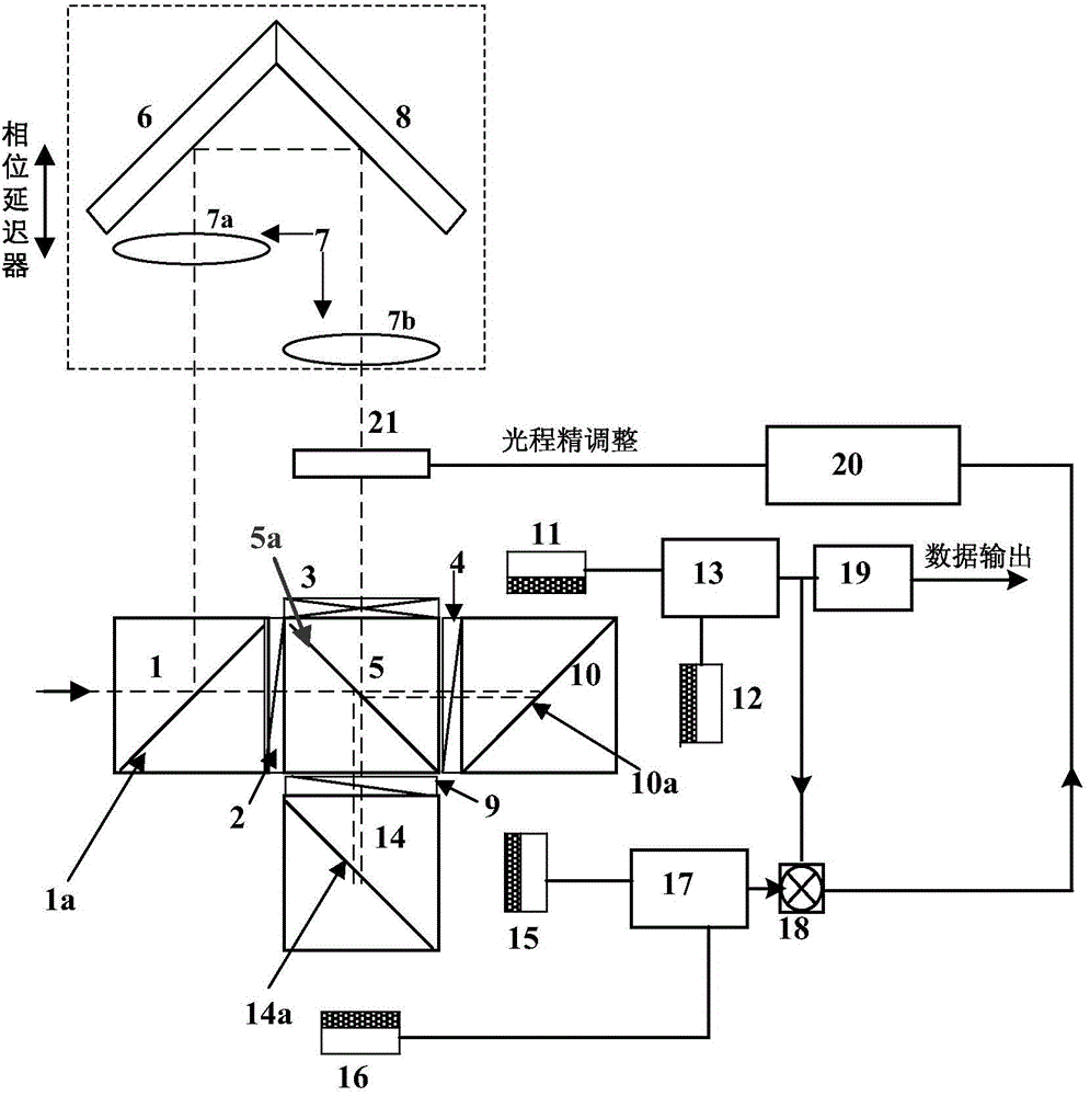
[0022] see first figure 1 , figure 1 It is a schematic diagram of the specific structure of the self-phase differential interference optical signal receiving device of the present invention. It is also a schematic diagram of the main structure of the embodiment of the present invention. It can be seen from the figure that a self-phase differential interference optical signal receiving device of the present invention comprises:

[0023] The first polarizing beam splitter 1, the first polarizing beam splitting surface 1a of the first polarizing beam splitter 1 is 45° to the advancing direction of the input circularly polarized light, and the first polarizing beam splitter 1 converts the input The circularly polarized light is divided into reflected light and tran...


PUM


Abstract

A self-phase differential interference optical signal receiving device is formed by a block-shaped polarization beam combiner, a reflector, a pupil imaging lens group, a wave plate and a photoelectric detector. The self-phase differential interference optical signal receiving device adopts balanced receiving of light and real-time control on stationary-phase phase, is short in time delay distance and adjustable in differential circuit optical path, and can meet requirements for high-speed communication.

Description

technical field [0001] The invention relates to optical signal demodulation, in particular to a self-phase differential interference optical signal receiving device. Background technique [0002] In free space laser communication, when the laser transmits through the atmospheric channel, it is affected by factors such as atmospheric turbulence, and the wavefront of the beam is distorted and the quality is seriously degraded. Laser signal reception needs to overcome atmospheric turbulence. The methods currently used mainly include reducing the receiving aperture, adaptive optical wavefront correction, and self-differential reception of DPSK modulated signals. The invention adopts DPSK modulation for self-differential reception, does not need to add a local oscillator signal, has a simple and compact structure, is easy to realize, and is the development direction of optical receiving signals in laser communication in the future. [0003] The previous technical research [1] (...

Claims


Application Information

Patent Timeline
Patent Type & Authority Patents(China)
IPC IPC(8): H04B10/61G02B27/28
Inventor 马小平孙建锋职亚楠鲁伟刘立人周煜戴恩文
Owner SHANGHAI INST OF OPTICS & FINE MECHANICS CHINESE ACAD OF SCI
Learn More