
Method and device for near-far end carrier synchronization of frequency shift machine

A technology of carrier synchronization and frequency shifting machine, which is applied in the field of frequency shifting machine, can solve the problems such as the inability to achieve zero intermediate frequency, achieve the effect of improving performance and realizing carrier synchronization

Active Publication Date: 2015-05-13
福建京奥通信技术有限公司
View PDF5 Cites 0 Cited by
  • Summary
  • Abstract
  • Description
  • Claims
  • Application Information

AI Technical Summary

Problems solved by technology

[0006] The technical problem to be solved by the present invention is to provide a carrier synchronization method and device for near and far ends of a frequency shifter, so as to solve the problem that the zero intermediate frequency cannot be achieved as described in the background technology

Method used


Image

  • Method and device for near-far end carrier synchronization of frequency shift machine
  • Method and device for near-far end carrier synchronization of frequency shift machine
  • Method and device for near-far end carrier synchronization of frequency shift machine

Examples


Embodiment Construction

[0044] The present invention will be further described in conjunction with the accompanying drawings and specific embodiments.

[0045] First briefly introduce the I and Q signals used in the present invention: the earliest communication is an analog communication, assuming that the carrier is cos(a), and the signal is cos(b), then by phase-constructed spectrum shift, it is obtained:

[0046] cos(a)*cos(b)= 1 / 2[cos(a+b)-cos(a-b)]

[0047] In this way, two signals are generated under the a carrier, a+b and a-b, and for transmission, only one signal is needed, that is to say, one of the two can be selected, and the other is useless and needs to be filtered out. But in fact, the filter is not ideal, and it is difficult to completely filter out the other one, so because of the existence of another frequency band, a lot of frequency band resources are wasted.

[0048] After entering the digital age, only one signal frequency is transmitted at a certain moment, such as 0, assumed t...


PUM


Abstract

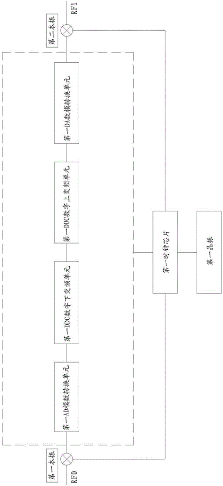
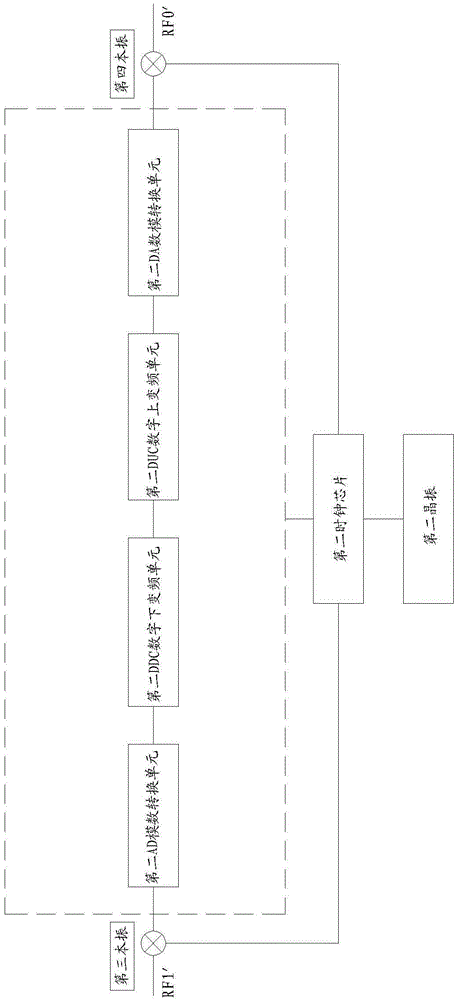
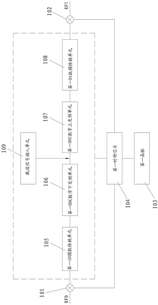
The invention relates to a frequency shift machine, in particular to near-far end carrier synchronization of the frequency shift machine. A method for the near-far end carrier synchronization of the frequency shift machine includes the following steps: step 1 a carrier signal is inserted before digital up conversion (DUC) of a near-end machine, and the carrier signal is a sine wave digital signal with I = c and Q = 0, wherein 0 <= c <= 0.5; step 2 the carrier signal is shifted in frequency to a frequency point which is almost the same as frequency RF0 of a radio frequency signal received by the near-end machine on a far-end machine through calculation of frequency deviation value and frequency deviation compensation value of the near-end machine and the far-end machine, through special formula: wherein the RF0 is the frequency of the radio frequency signal received by the near-end machine, the RF1 is frequency of a radio frequency signal sent by the near-end machine, and frequency deviation compensation is performed according to the formula so as to enable the frequency RF0 of the radio frequency signal received by the near-end machine to be the same as frequency RF0' of a radio frequency signal sent by the far-end machine. The method and the device are applied to the near-far end carrier synchronization of the frequency shift machine.

Description

technical field [0001] The invention relates to a frequency shifting machine, in particular to the near-far end carrier synchronization of the frequency shifting machine. Background technique [0002] In order to overcome the problems of self-excitation and omnidirectional coverage of the same-frequency repeater, frequency-shifting repeater is widely used. The basic principle is to convert the network signal of a certain frequency band to other frequency bands at the near end through the frequency converter. After the amplification process, it is transmitted through the antenna, and the antenna of the same frequency band is used to receive at the remote end. After processing, the frequency is down-converted to the original frequency band by the frequency converter, and then the omnidirectional or directional antenna is used to cover the target area. The processing of the uplink signal is the opposite. The above process is often implemented by frequency shifting machines, wh...

Claims


Application Information

Patent Timeline
Patent Type & Authority Patents(China)
IPC IPC(8): H04L27/26H04L25/03
Inventor 康忠林卓开泳叶天宝高心炜
Owner 福建京奥通信技术有限公司
Learn More