
Gas spring for sliding refractory gate valve

A technology of gas spring and gate valve, which is applied in the direction of spring, spring/shock absorber, shock absorber-spring combination, etc., which can solve the problems that the sliding mechanism cannot be allowed to work and the applied force is large, so as to achieve compact design and prevent leakage Effect

Active Publication Date: 2012-07-18
NUTBERRY
View PDF5 Cites 0 Cited by
  • Summary
  • Abstract
  • Description
  • Claims
  • Application Information

AI Technical Summary

Problems solved by technology

[0010] For some mechanisms, the force exerted by the gas spring at high temperature is too great to allow the sliding mechanism to work

Method used


Image

  • Gas spring for sliding refractory gate valve
  • Gas spring for sliding refractory gate valve
  • Gas spring for sliding refractory gate valve

Examples


Embodiment Construction

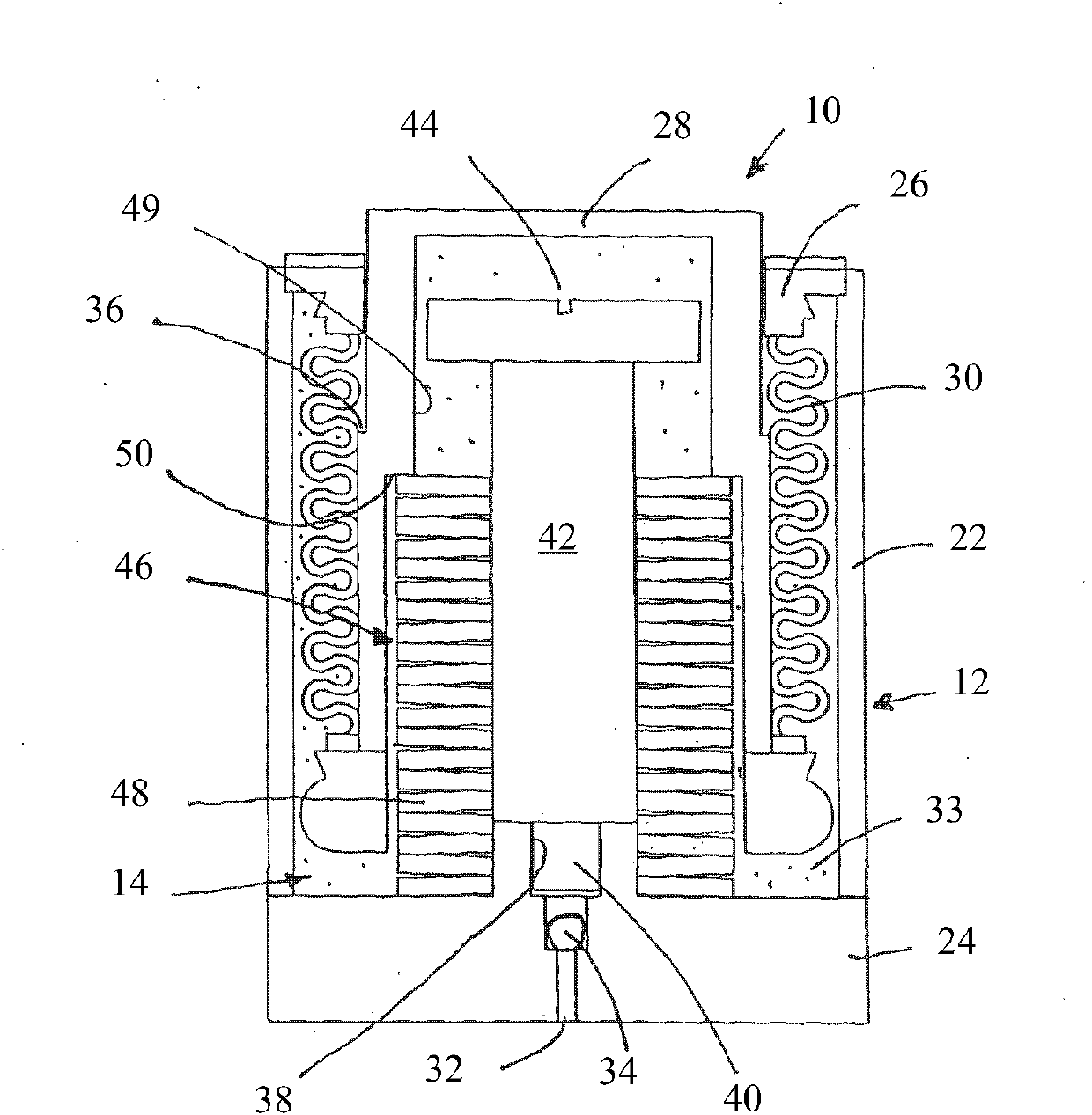
[0024] refer to figure 1 , the exemplary gas spring 10 includes a metal tube 22 onto which a base 24 and a guide sleeve 26 are welded to define the container 12 . A plunger 28 extends through a bore in guide sleeve 26 . Stainless steel bellows 30 is welded at one end to guide sleeve 26 and at the other end to plunger 28 , thereby defining a closure or seal with plunger 28 , metal tube 22 , base 24 and guide sleeve 26 outside bellows 30 and inside container 12 space14.

[0025] The base 24 is provided with an injection hole 32 and a valve 34, whereby the closed space can be filled under pressure with an inert gas 33, such as nitrogen. Gases are represented by dots in the diagram.

[0026] During use, gas pressure acts upwardly on the plunger 28, as shown in the figures.

[0027] The plunger 28 has a circumferential stop 36 for figure 1 The direction shown upwards limits the maximum extension of the plunger.

[0028] The base 24 is provided with a threaded bore 38 that rec...


PUM


Abstract

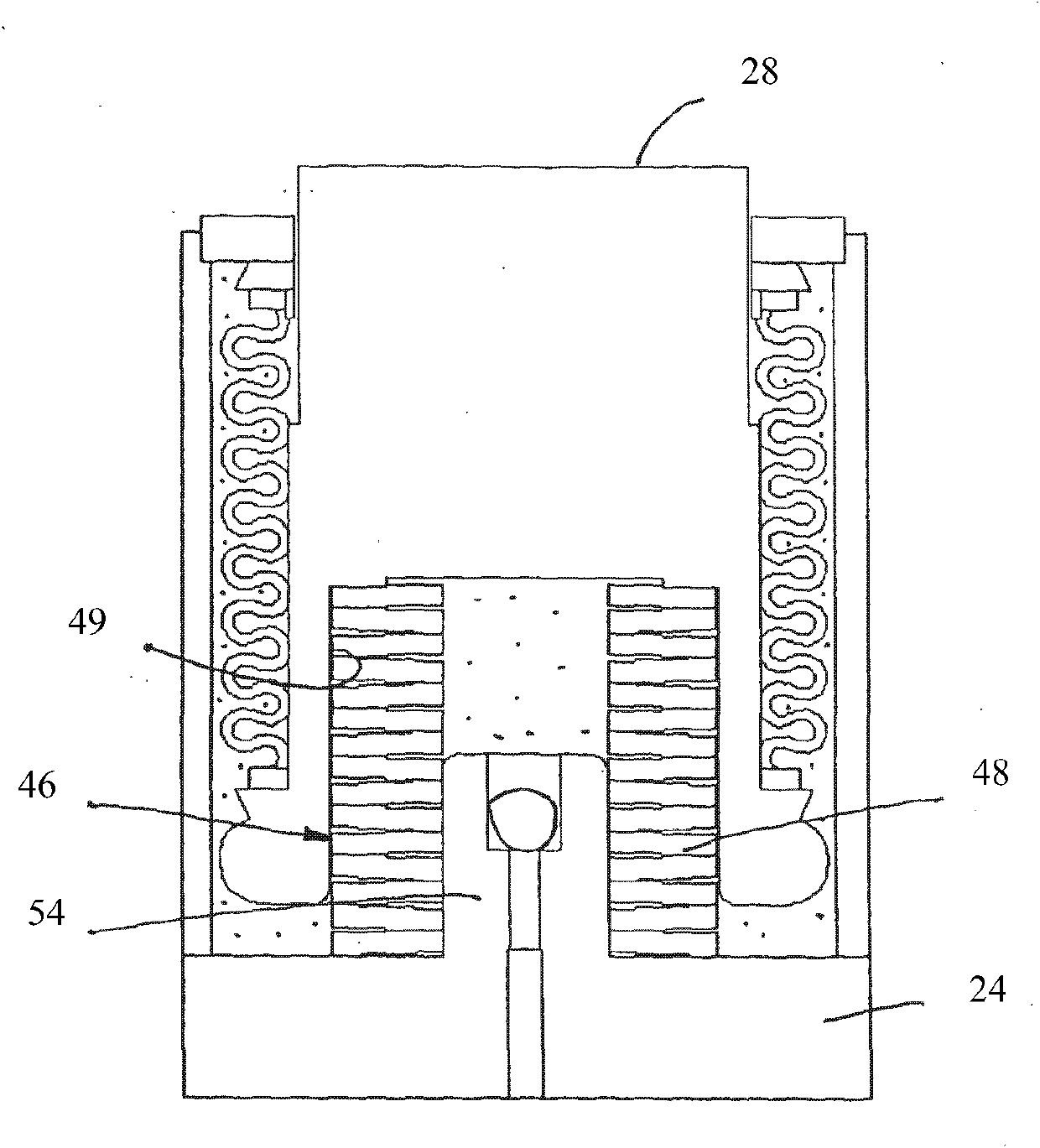
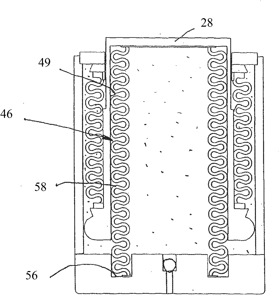
A gas spring (10) for a sliding refractory gate valve, comprising a container (12), a ram (28) which is extendable relative to the container, a bellows (30) connected at one end to the ram and at the other end to a part of the container, a gas (33) within the container outside the bellows and acting to compress the bellows and extend the ram, wherein the ram has a blind internal bore (49) and a mechanical compression spring (46) is at least partially disposed in the bore so as to be interposed between the ram and the container and also acting to extend the ram.

Description

technical field [0001] The invention relates to a gas spring for a sliding fire-resistant gate valve. Background technique [0002] Gas springs (also known as TDE (Thermo Dynamic Element)) are used in sliding gate valve mechanisms that control the flow of molten steel during continuous casting. Springs inside the mechanism are used to clamp together the face-to-face opposing sliding refractory panels. Each plate has a hole in the middle; when the two holes are aligned, the flow of molten steel is maximum. The hole diameter increases or decreases according to the position of these plates, thus determining the flow of molten steel. [0003] The springs have to provide enough force to keep the molten steel out of the way between these plates (known as flashing), which can cause the molten steel to leak, which is extremely dangerous and expensive. The sliding of the refractory board is powered by hydraulic pressure. [0004] A gas spring (TDE) basically consists of a metal p...

Claims


Application Information

Patent Timeline
Patent Type & Authority Applications(China)
IPC IPC(8): B22D41/40F16F13/00
CPCF16F9/0209F16F13/002B22D41/40
Inventor 安东尼·鲁伯特·蒙特贝洛
Owner NUTBERRY
Learn More