Water-cleaning gluing head for multi-component polyurethane needle valve

A polyurethane and glue-applying head technology, applied in the directions of coating, cleaning hollow objects, cleaning methods and utensils, etc., can solve the problem of not being able to use water for cleaning, and achieve the effects of reducing cleaning times, saving energy and improving production efficiency

Active Publication Date: 2012-07-25
DALIAN HUAGONG INNOVATION TECH
View PDF4 Cites 35 Cited by
  • Summary
  • Abstract
  • Description
  • Claims
  • Application Information

AI Technical Summary

Problems solved by technology

[0003] In order to solve the problem that the existing two-component polyurethane gluing head must be cleaned with a solvent and cannot be cleaned with water, the present invention provides a multi-component polyurethane needle valve water cleaning gluing head

Method used


Image

  • Water-cleaning gluing head for multi-component polyurethane needle valve
  • Water-cleaning gluing head for multi-component polyurethane needle valve
  • Water-cleaning gluing head for multi-component polyurethane needle valve

Examples


specific Embodiment approach 1

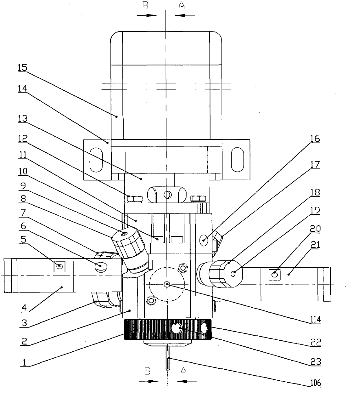
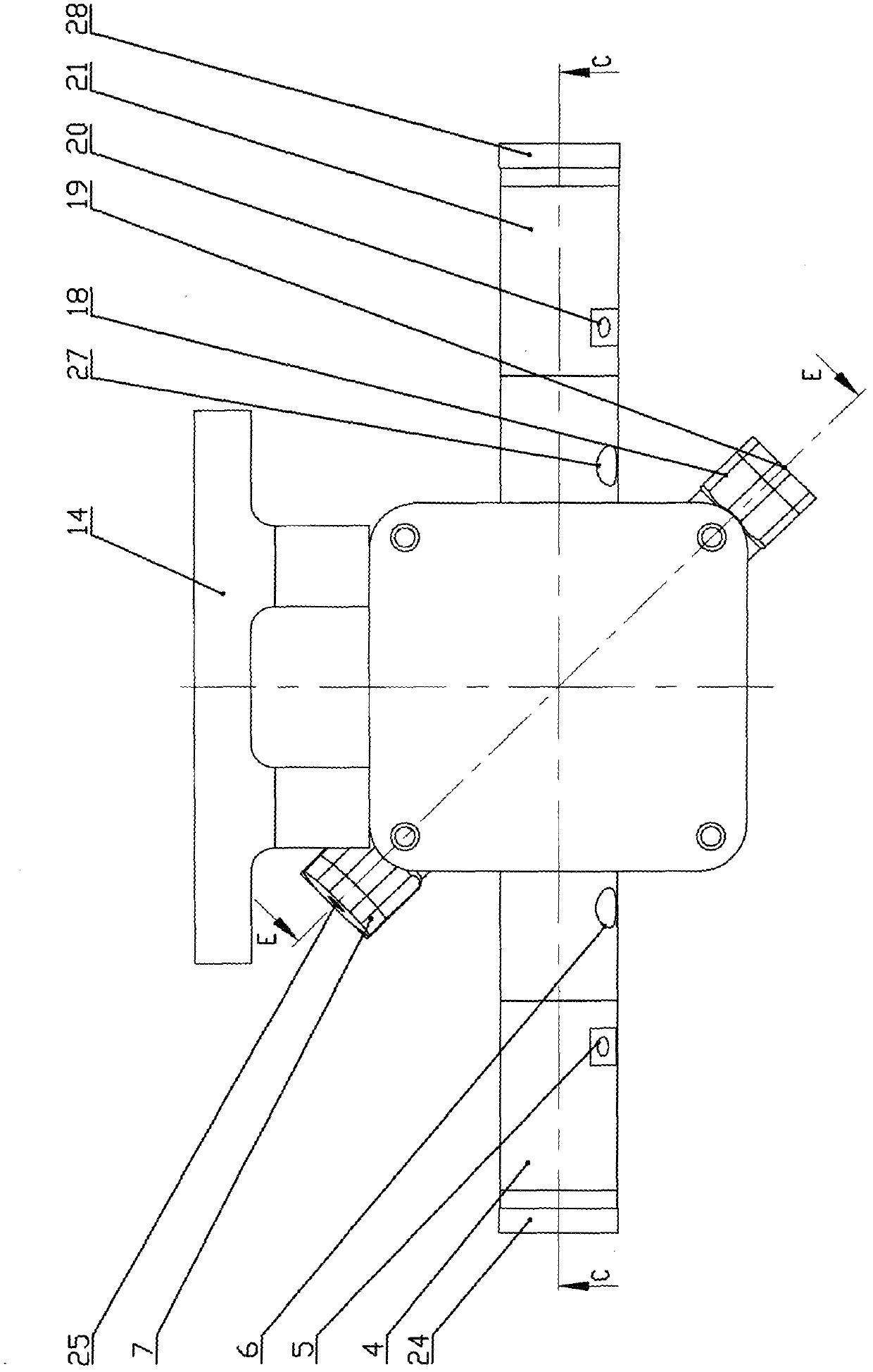
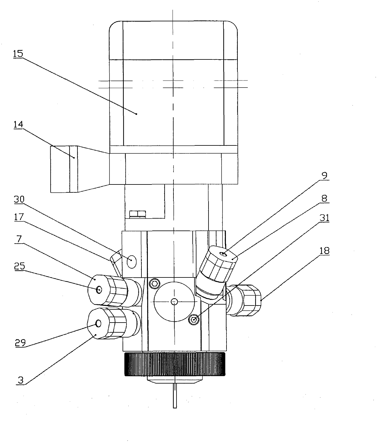
[0023] Specific implementation mode one: as figure 1 , figure 2 , image 3 , Figure 4 , Figure 5 , Figure 6 and Figure 7 As shown, the multi-component polyurethane needle valve water cleaning gluing head of the present invention includes a motor 15, a transmission shaft 61, a stirring blade 39, a cup moving part 1, a valve seat 2, an intermediate valve body 11, an upper valve body 13, Valve fixing plate 14, component A needle valve 4, component B needle valve 21, water valve A3, water valve B17, water valve C8, water valve D18 and air valve 7, etc., are connected together with screws or threads. Turn on the metering pump to supply glue, and the polyurethane glue of two components, A and B, enters the A chamber 107 and the B chamber 108 from the glue inlet hole 6 of the component A and the glue inlet hole 65 of the B component respectively. Needle B110, the polyurethane glue of two components A and B respectively enters the C cavity 109 through the A glue inlet nozzl...

specific Embodiment approach 2

[0031] Specific implementation mode two: if in figure 1 Add a glue inlet channel to the position shown by the double-dot dash line, and add a C component needle valve to become a three-component polyurethane needle valve water cleaning gluing head. The three components (A component, B component , C) polyurethane enters C cavity 109 from A component needle 4, B component needle valve 21 and C component needle valve respectively, and other structures remain unchanged. Water cleaning, compressed air cleaning, and three-component polyurethane glue feeding methods are the same as those in Embodiment 1.

[0032] working principle

[0033] Turn on the metering pump to supply the glue, the polyurethane glue of the two components A and B enters the cavity C through the glue inlet nozzle of A and the glue inlet nozzle of B respectively, and the motor drives the stirring blade to rotate, and the polyurethane glue of the two components A and B The glue is mixed evenly and starts to reac...


PUM


Abstract

The invention relates to a water-cleaning gluing head for a multi-component polyurethane needle valve, in order to solve the problem that the traditional double-component polyurethane gluing head must be cleaned with a solvent and cannot be cleaned with water. The multi-component polyurethane water-cleaning gluing head comprises a motor, a transmission shaft, a stirring blade, a cup moving part, a valve base, a middle valve body, an upper valve body, a valve fixing plate, an component needle valve A, a component needle valve B, a water valve A, a water valve B, a water valve C, a water valve D and an air valve, wherein a cup base is connected with the valve base; a sealing ring A, a sealing ring B and a sealing ring C are mounted on an outer ring of a moving cup body; a check ring, a sealing circle and a sealing ring are mounted on an inner ring of the moving cup body; and a fixing sleeve is mounted between an ending opening on the cup base and the valve base. The manner of cleaning with water and then cleaning with compressed air is realized; the cleaning time is shortened; the threat to the health of operators and the environmental pollution caused by the solvent are eliminated; the structure is simple and compact; the mounting is convenient; the repairing is quick; and the stability is increased.

Description

technical field [0001] The invention relates to a multi-component polyurethane needle valve water cleaning gluing head. Background technique [0002] At present, there are many types of two-component polyurethane glue applicators at home and abroad. According to the structure of the valve body switch, it can be divided into shaft motion, cup motion, and external rubber valve control. When the gluing head has a long working interval or stops working, in order to prevent the gluing head from being blocked, the gluing head must be cleaned frequently to clean the mixed two-component polyurethane glue in the glue chamber. The cleaning of the existing gluing head is only Solvent can be used for cleaning, and each cleaning requires a large amount of solvent, which increases production costs. Solvents pose a greater threat to the health of operators, pollute the environment, waste energy, and are flammable. Operation is also very time-consuming and laborious. At present, there is ...

Claims


Application Information

Patent Timeline
Patent Type & Authority Applications(China)
IPC IPC(8): B05C11/00B08B3/10B08B5/02B08B9/28
Inventor 韩毅军
Owner DALIAN HUAGONG INNOVATION TECH
Why Eureka
Try Eureka