
Process method for producing steel shots by ladle-casting slag pelletization

A process method and casting slag technology, which is applied in the field of online recycling of high-temperature liquid ladle casting slag (ladle slag), can solve the problems of large burning loss of metallic iron, high production cost, and large environmental pollution

Active Publication Date: 2012-07-25
MAGANG (GROUP) HOLDING CO LTD
View PDF6 Cites 15 Cited by
  • Summary
  • Abstract
  • Description
  • Claims
  • Application Information

AI Technical Summary

Problems solved by technology

The main problems of the above methods are: the pollution of the working environment during the slag turning and transshipment process is relatively high, and the treatment cost is relatively high; the metal iron is burned and the smoke and dust pollution is serious when cutting and processing slag steel; the tailing slag is used less, which causes great environmental pollution.
At present, the production process of steel shot is mainly: using high-quality scrap steel and alloy, after being smelted in an electric furnace, granulating, and then undergoing multiple heat treatments and screening to produce qualified steel shot, the production cost is relatively high

Method used


Image

  • Process method for producing steel shots by ladle-casting slag pelletization
  • Process method for producing steel shots by ladle-casting slag pelletization

Examples


Embodiment Construction

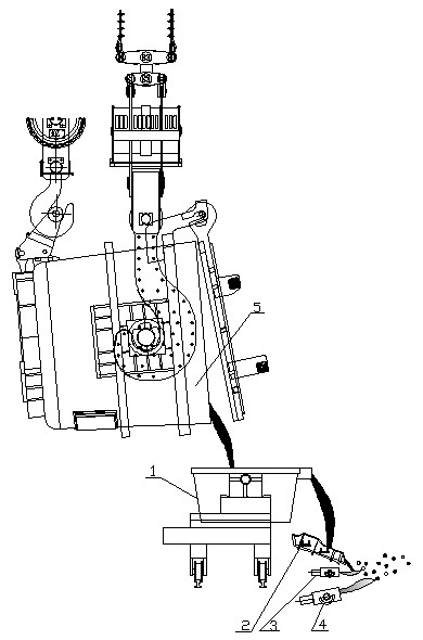
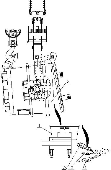
[0009] The ladle slag granulation device in the process of the present invention is mainly composed of a tiltable temperature-rising liquefaction device 1 , an intermediate launder 2 , a pneumatic granulator 3 , and a controlled cooling atomizer 4 . The function of the tiltable liquefaction heating device 1 is to heat the ladle slag so that the ladle slag (including residual steel) has good fluidity and can evenly flow out through the middle launder. The function of the middle launder 2 is to control the width and velocity of the stream, and adjust the distance between the ladle slag stream and the pneumatic granulator 3 . The function of the pneumatic granulator 3 is to control the velocity and shape of the air outlet, crush the ladle slag stream into fine droplets, and make the droplets fly with the airflow. The function of the cooling control atomizer 4 is to extend the flight distance of the steel grains and slag balls, strengthen the control of the cooling speed of the st...


PUM


Abstract

The invention discloses a process method for producing steel shots by ladle-casting slag pelletization. The process method comprises the following steps that: a) a ladle nozzle is closed after the steel casting is finished, a ladle is lifted to be above a temperature-rising liquefying device, the ladle is tilted after alignment, and the lade slag is poured into the temperature-rising liquefying device; b) a power supply of the temperature-rising liquefying device is switched-on to heat and increase the temperature, and after the ladle slag is completely molten and the temperature is increased, the temperature-rising liquefying device is tilted to enable the ladle slag to flow out slowly; c) the ladle slag forms stream through a middle flow chute and falls off freely from the front part of a pneumatic pelletizer, the pneumatic pelletizer sprays out high-speed gas flow to crush the ladle slag stream into fine liquid drops, the liquid drops fly along with the gas flow, and simultaneously, a controlled-cooling atomizer distributed below the pneumatic pelletizer sprays out gas-water mixed flow to push liquid drops of the ladle slag to fly continuously and carries out enhanced cooling on the liquid drops of the ladle slag, so that the fine liquid drops are cooled and solidified into steel shots and small slag balls in the flying process, and are prevented from being melted and bonded together after falling to the ground. The method effectively improves the utilization value of the ladle slag.

Description

technical field [0001] The invention relates to on-line resource processing of high-temperature liquid ladle casting residue (ladle slag). Background technique [0002] Ladle casting slag is generally composed of furnace slag, deoxidized product, refining slag, thermal insulation agent, etc., and contains part of residual molten steel. Generally, there is a layer of slag crust formed on the slag surface, and the fluidity is poor. [0003] At present, most domestic steel mills use the traditional process to process ladle slag. The process is: after pouring steel, pour the ladle casting slag into the slag tank, transfer it to the hot pouring tank, or pull it to the slag yard to turn the slag, and wait for it to be turned over. After the ladle slag is completely cooled, the scrap steel in the slag is separated and recycled by means of smashing, cutting, breaking, and sorting, and the tailing slag is discarded or flowed into a small workshop for wet grinding and sorting. The p...

Claims


Application Information

Patent Timeline
IPC IPC(8): C21B3/08B01J2/04C04B5/02
CPCC21B2400/024C21B2400/026C21B2400/062Y02P10/20
Inventor 蒋育翔邱艳生
Owner MAGANG (GROUP) HOLDING CO LTD
Learn More