
Railway vehicle braking cylinder piston assembly

A technology for railway vehicles and brake cylinders, applied in the direction of brake actuators, gear transmission mechanisms, mechanical equipment, etc., can solve the problems of affecting the braking performance of railway vehicles, straining the inner wall of the brake cylinder, and leakage of compressed air. Prevent the inner wall of the brake cylinder from being pulled, prolong the reliable use time, and prevent the effect of partial wear

Active Publication Date: 2012-07-25
CRRC QIQIHAR ROLLING CO LTD
View PDF5 Cites 8 Cited by
  • Summary
  • Abstract
  • Description
  • Claims
  • Application Information

AI Technical Summary

Problems solved by technology

When the piston is working, there is a lack of grease between the upper part of the sealing ring and the inner wall of the brake cylinder, and it will wear out quickly under the condition of poor lubrication; at the same time, the piston has no guide belt, and the metal piston body often pulls the inner wall of the brake cylinder; After the inner wall of the moving cylinder is worn out, the sealing ring will also wear out faster
After the sealing ring is worn, the compressed air leaks when the brake cylinder is working, which affects the braking performance of the railway vehicle

Method used


Image

  • Railway vehicle braking cylinder piston assembly
  • Railway vehicle braking cylinder piston assembly
  • Railway vehicle braking cylinder piston assembly

Examples


Embodiment Construction

[0014] The present invention will be described in detail below in conjunction with the accompanying drawings and embodiments.

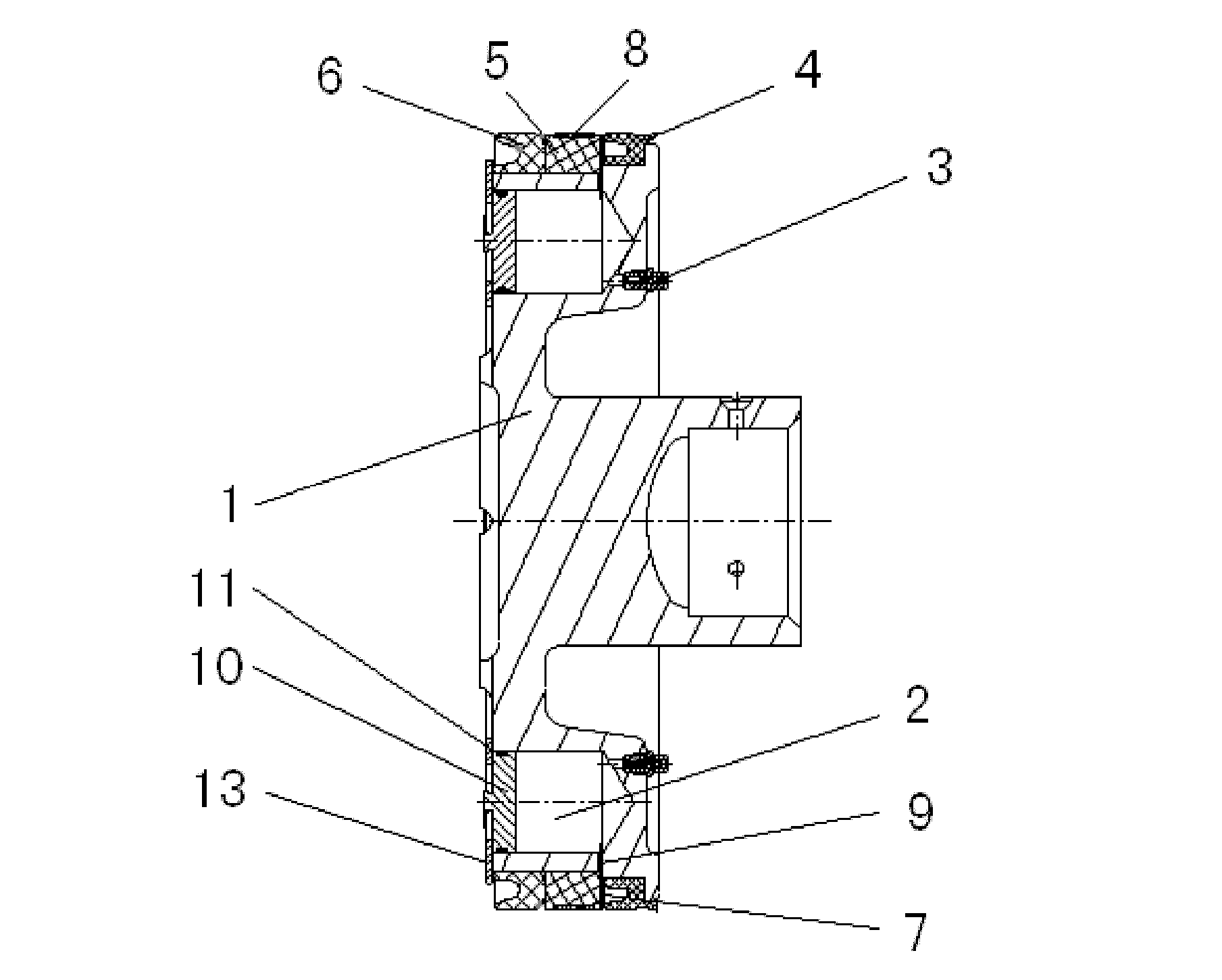
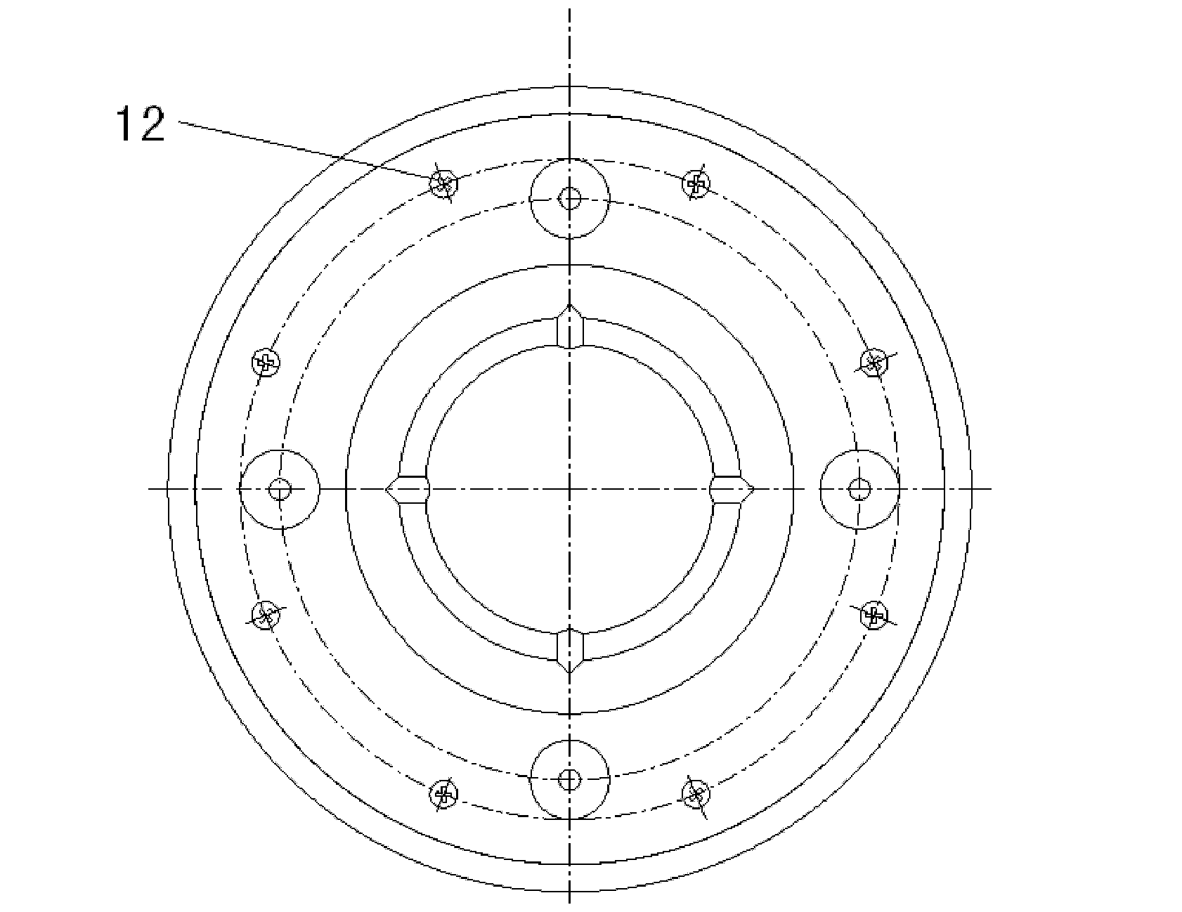
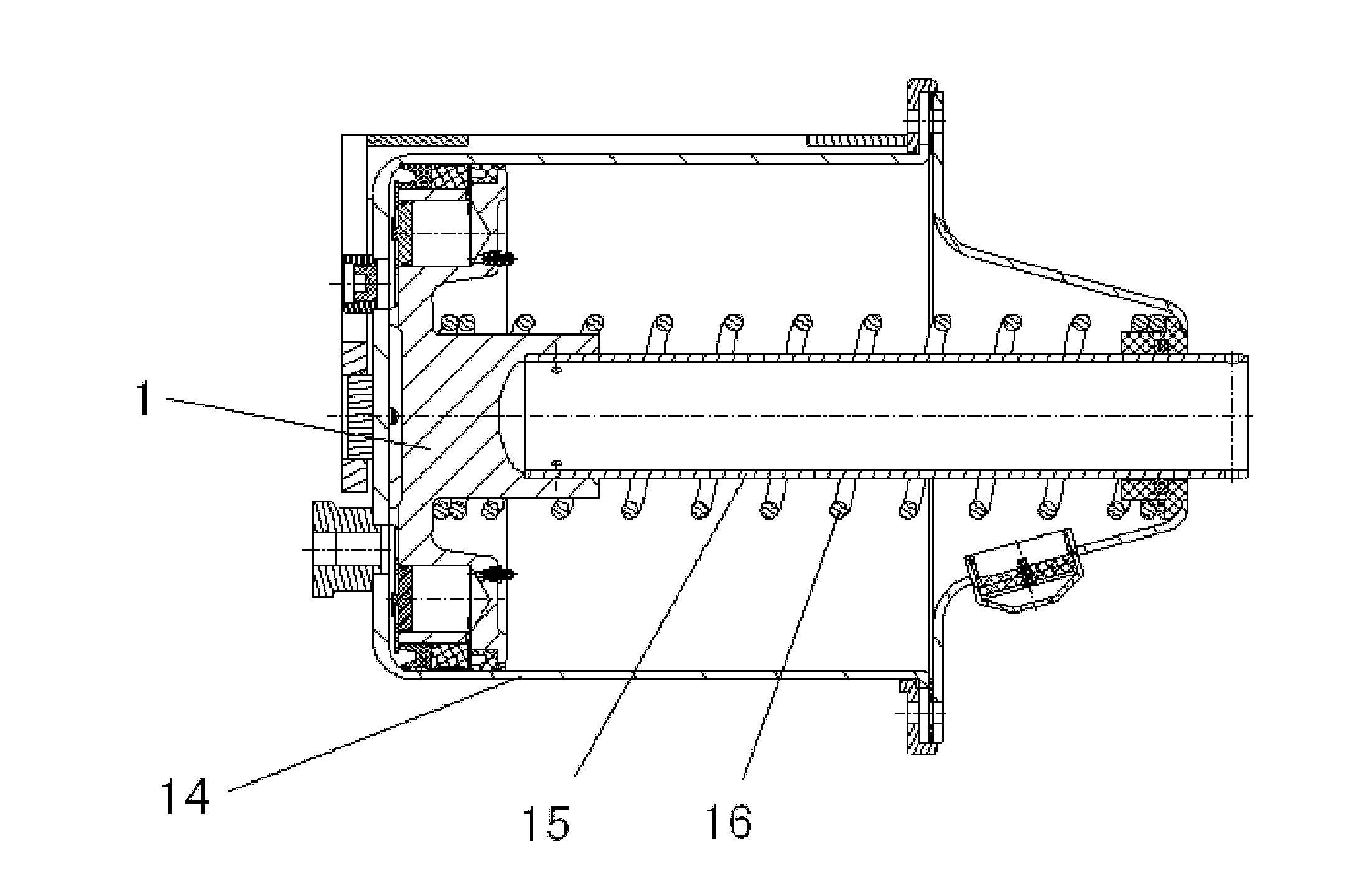
[0015] like figure 1 , figure 2 As shown, the present invention mainly adopts the grease retention technology, which includes a piston body 1, and 2 to 6 oil storage chambers 2 are arranged at intervals at the periphery of the piston body 1, and each oil storage chamber 2 and the inner side of the piston body 1 Each oil storage chamber 2 is respectively provided with a one-way passage oil cup 3, and the oil storage chamber 2 is replenished with grease through the oil cup 3. On the outer wall surface of the piston body 1, a rear seal ring 4, a spacer ring 5 and a front seal ring 6 are set sequentially from the inside to the outside. The inner diameter surface and both sides of the spacer ring 5 are provided with guides for circulating and distributing grease. The oil groove 7; the outside of the spacer ring 5 is also provided with a guide belt 8, wh...


PUM


Abstract

The invention relates to a railway vehicle braking cylinder piston assembly, which is characterized by comprising a piston body, wherein 2 to 6 oil storing cavities are arranged on the periphery of the piston body at intervals, and an oil cup with a one-way passage corresponding to the oil storing cavities is respectively arranged between the oil storing cavities and the inner side of the piston body. A rear sealing ring, a space ring and a front sealing ring are sequentially sleeved on the circumferential outer wall surface of the piston body from inside to outside, oil guiding grooves for lubricating grease circulating and distributing are arranged on the inner-diameter surface and two lateral surfaces of the space ring, and a guiding belt is further sleeved outside the space ring. An oil through hole is respectively arranged between the outer cylindrical surface of the piston body and the oil storing cavities, an oil cavity piston body is respectively arranged between the outer side of the piston body and the oil storing cavities, an O-shaped sealing ring is arranged between the oil cavity piston body and the piston body, and a pressing board is fixedly arranged outside the oil cavity piston body through screws. The railway vehicle braking cylinder piston assembly has good lubricating effect, prevents the piston body from pulling the inner wall of a braking cylinder, and can improve work reliability of the braking cylinder. The railway vehicle braking cylinder piston assembly can be widely used in railway vehicle braking systems.

Description

technical field [0001] The invention relates to a piston composition in the field of mechanical equipment, in particular to a piston composition of a railway vehicle brake cylinder which adopts two-stage sealing and automatically performs lubricating grease compensation. Background technique [0002] The railway vehicle brake cylinder is a single-acting cylinder, and the piston rod is pushed out horizontally during operation. The traditional brake cylinder piston is made of cast iron or carbon steel piston body, and a Y-shaped sealing ring is installed for sealing, and it is sealed by applying grease on the inner wall of the brake cylinder and installing an oil-soaked felt ring lubrication sleeve on the piston body. lubricating. When this kind of brake cylinder is working, the grease on the inner wall of the cylinder is squeezed to the bottom and front end of the brake cylinder respectively; when the temperature is high, the viscosity of the grease on the inner wall of the ...

Claims


Application Information

Patent Timeline
IPC IPC(8): F16D65/14F16D121/04F16D125/06F16D125/08
Inventor 陈时虎于建刚
Owner CRRC QIQIHAR ROLLING CO LTD
Learn More