Roadbed dynamic response in-situ test system and roadbed dynamic response in-situ test method

A technology of subgrade dynamics and in-situ testing, applied in the field of subgrade testing, to achieve the effect of actively controlling test conditions and realizing on-site prototype testing

Inactive Publication Date: 2012-07-25
WUHAN UNIV OF SCI & TECH +1
View PDF9 Cites 14 Cited by
  • Summary
  • Abstract
  • Description
  • Claims
  • Application Information

AI Technical Summary

Problems solved by technology

[0005] The purpose of the present invention is to overcome the deficiencies of the existing indoor model test and field test, and the purpose is to provide a roadbed dynamic response in-situ test system and test method that can not only realize the field test, but also actively control the test conditions

Method used


Image

  • Roadbed dynamic response in-situ test system and roadbed dynamic response in-situ test method
  • Roadbed dynamic response in-situ test system and roadbed dynamic response in-situ test method
  • Roadbed dynamic response in-situ test system and roadbed dynamic response in-situ test method

Examples


Embodiment 1

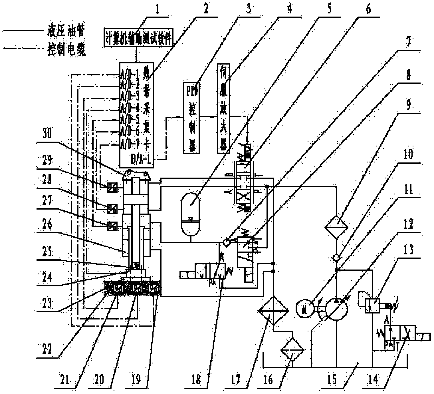
[0049] An in-situ test system and test method for roadbed dynamic response. The test system described is figure 1 As shown: the oil pump 12 is coaxially connected with the motor 11, the oil suction port of the oil pump 12 communicates with the oil tank 15 through the oil pipe, and the oil pressure port of the oil pump 12 connects with the oil inlet of the relief valve 13 and the inlet of the first check valve 10 through the oil pipe. The oil ports communicate with each other, the oil outlet of the relief valve 13 communicates with the oil tank 15 through the oil pipe, the control port of the relief valve 13 communicates with the A port of the second electromagnetic reversing valve 14, and the T port of the second electromagnetic reversing valve 14 Communicate with the oil tank 15 through the oil pipe, and the P port of the second electromagnetic reversing valve 14 is blocked; The oil outlet communicates with the P port of the electro-hydraulic servo valve 6 and the P port of ...

Embodiment 2

[0082] An in-situ test system and test method for roadbed dynamic response. Except following technical parameter, all the other are with embodiment 1.

[0083] The soil pressure sensor 21, acceleration sensor 20 and speed sensor 19 buried in the roadbed 22 means that the earth pressure sensor 21, acceleration sensor 20 and speed sensor 19 are placed at a depth of 200-1000 mm from the surface of the roadbed 22;

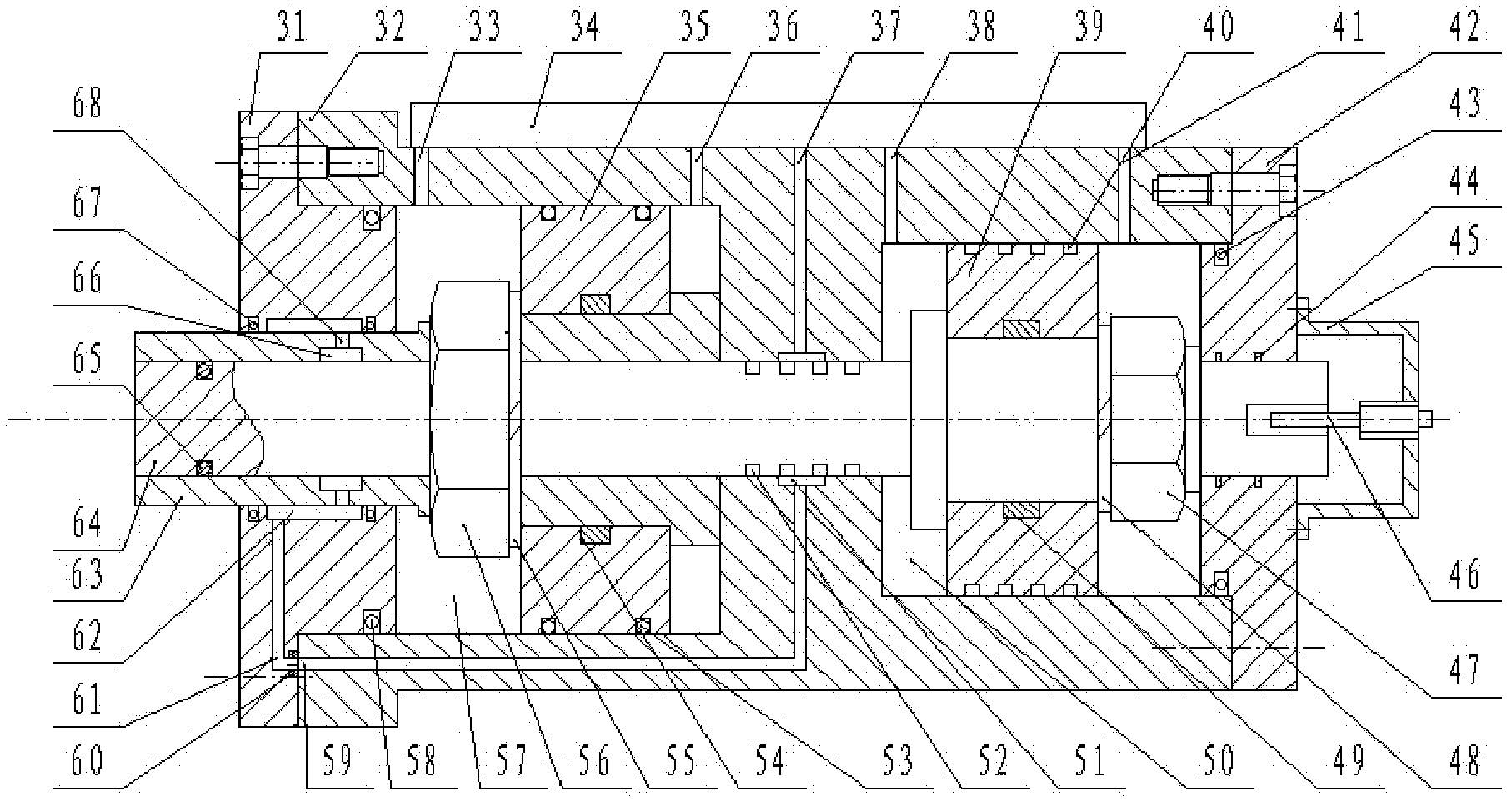
[0084] The outer wall of the dynamic pressure piston 39 is provided with 4 to 5 first balance grooves 40, and there are 5 to 6 first balance grooves 40 on the dynamic pressure piston rod 64 at the contact part of the central through hole of the cylinder partition wall. a second balance tank 52;

[0085] The width of the first leakage oil annular groove 62 is 1.5-2.0 times of the stroke of the static pressure piston 35 .

[0086] Owing to adopting above-mentioned technical scheme, this specific embodiment has following positive effect:

[0087] 1. This specific embod...


PUM


Abstract

The invention relates to a roadbed dynamic response in-situ test system and a roadbed dynamic response in-situ test method. The scheme includes that an oil pump (12) is respectively communicated with a P-port of an electro-hydraulic servo valve (6) and a P-port of a first electromagnetic directional valve (8) through a one-way valve (10), an A-port and a B-port of the electro-hydraulic servo valve (6) are correspondingly communicated with a third and fourth operational oil ports (38 and 41) of a two-stage servo hydraulic cylinder (26), and an A-port of the first electromagnetic directional valve (8) is respectively communicated with a second operational oil port (36) of the two-stage servo hydraulic cylinder (26), an A-port of an electromagnetic ball valve (18) and an energy accumulator (5) through a second one-way valve (7). An operational end of the two-stage servo hydraulic cylinder (26) is tightly pressed on the surface of a roadbed (2) through a load sensor (24) and an excitation disc (23), all sensors in the system are electrically connected with a data acquisition card (2), and the data acquisition card (2) and computer auxiliary testing software (1) are mounted in a computer. Using the roadbed dynamic response in-situ test system and the roadbed dynamic response in-situ test method can not only realize in-situ prototype tests but also actively control test conditions.

Description

technical field [0001] The invention belongs to the technical field of roadbed testing. In particular, it relates to an in-situ test system and test method for subgrade dynamic response. Background technique [0002] High-speed railways have very high requirements on the smoothness and stability of the track. The settlement and deformation of the subgrade as the basis for carrying the weight of the track structure and the load of the train will definitely affect the smoothness and stability of the track. Therefore, in order to ensure the smooth and safe operation of high-speed trains, the dynamic problem of track subgrade under the dynamic load of trains is a basic issue that must be considered in the construction of high-speed railways. [0003] The subgrade not only bears the static load of the superstructure, but also suffers from repeated dynamic loads when the train is running. High-speed trains will not only increase the dynamic load and vibration frequency of the tr...

Claims


Application Information

Patent Timeline
Patent Type & Authority Applications(China)
IPC IPC(8): G01N3/36
Inventor 曾良才陈新元陈善雄姜领发湛从昌余飞傅连东秦尚林许锡昌毛季陈昶龙万园郑飞龙雷斌
Owner WUHAN UNIV OF SCI & TECH
Why Eureka
Try Eureka