Method and equipment for confirming CT (Computed Tomography) scanning position in dangerous goods inspection system

A CT scanning and inspection system technology, applied in the field of radiation inspection, can solve the problems of radiation residue, heavy equipment, unsuitable automatic and fast inspection, etc., and achieve the effect of improving the detection speed

Active Publication Date: 2012-07-25
TSINGHUA UNIV +1
View PDF4 Cites 12 Cited by
  • Summary
  • Abstract
  • Description
  • Claims
  • Application Information

AI Technical Summary

Problems solved by technology

Electromagnetic methods are inherently susceptible to adverse effects from metal packaging and packaging of thicker materials
Therefore, in the actual situation of complex packaging materials, the electromagnetic method has certain limitations
[0007] 3) The use of the neutron inspection method will cause the phenomenon of "neutron activation", that is, the inspected liquid items that have passed the neutron inspection will have radiation residues
With the development of CT technology, industrial CT for non-destructive testing and baggage CT for security inspection have emerged. These CT expansion technologies are still aimed at obtaining tomographic images showing the internal structure of objects, relying on manual analysis of the structure. Carry out analysis to determine whether the inspected object is a dangerous article, not suitable for automatic and rapid inspection
In addition, the above-mentioned CT-type security inspection equipment, because of its wide range of objects to be inspected, leads to high cost, heavy equipment, and difficulty in popularization and application.
[0011] To sum up, for rapid inspection of liquid objects, chemical methods, electromagnetic methods and neutron methods have the characteristics that they are not suitable for rapid security inspection. Using X-ray two-dimensional imaging technology and three-dimensional CT scanning imaging technology can only obtain performance The image of the internal structure of the item cannot provide sufficient basis for the automatic and safe inspection of liquid items

Method used


Image

  • Method and equipment for confirming CT (Computed Tomography) scanning position in dangerous goods inspection system
  • Method and equipment for confirming CT (Computed Tomography) scanning position in dangerous goods inspection system
  • Method and equipment for confirming CT (Computed Tomography) scanning position in dangerous goods inspection system

Examples


no. 1 approach

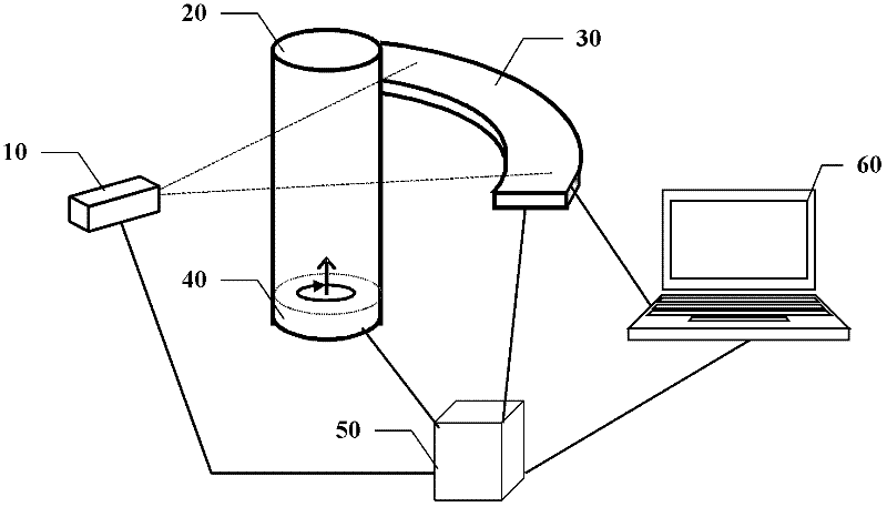
[0087] figure 1 is a schematic structural diagram of an inspection device according to an embodiment of the present invention.

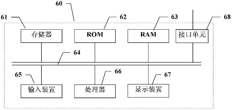
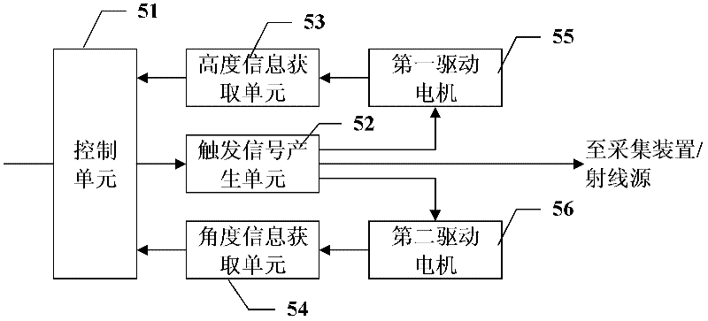
[0088] Such as figure 1 As shown, the inspection equipment according to this embodiment includes: a radiation source 10 that emits dual-energy X-rays for inspection, such as an X-ray machine; Detect the liquid object into the detection area, so that the radiation emitted by the ray source 10 can pass through the liquid object to be inspected; the detection and collection device 30 is a detector and a data collector with an overall module structure, which is used to detect the liquid object to be inspected. The dual-energy ray of the item obtains an analog signal, and converts the analog signal into a digital signal, thereby outputting the scanning data of the liquid item for high-energy X-rays and low-energy X-rays; the controller 50, which is used to control the synchronous work of various parts of the entire system ; and a computer data processor...

no. 2 approach

[0180] The above first embodiment describes the situation of detecting a single liquid item each time, and the operation process of simultaneously detecting multiple liquid items will be described in detail below with reference to FIGS. 15-18 . The difference between the second embodiment and the first embodiment is that because there are many liquid items, after the CT imaging is completed, the position of the imaging result displayed on the display corresponds to the position of the object on the carrying mechanism, so as to facilitate operation The officers figured out that the liquid item was a dangerous item. Figure 15A with Figure 15B A schematic diagram showing a reconstructed CT image in the case of detecting multiple liquid items according to the second embodiment of the present invention.

[0181] For example, the operator observes the object to be inspected on the carrying mechanism by looking down, which requires that the position of each object on the CT image ...

no. 3 approach

[0198] In order to further improve the detection efficiency and prevent the problem that the slender liquid objects to be inspected are directly placed on the carrying mechanism, which may cause instability during the inspection and affect the detection effect, the third embodiment proposes to place multiple objects in the divided bucket.

[0199] Therefore, the difference between the third embodiment and the second embodiment is that a divided bucket is used in the process of inspecting multiple objects. Attached below Figures 19-24 The specific operation process of the detection device according to this embodiment will be described in detail.

[0200] Figure 19 shows a side view of the divided barrel according to the present embodiment, Figure 20 shows a top view of the compartmented barrel, while Figure 21 A bottom view of the compartment bucket is shown.

[0201] Such as Figure 19 As shown, the compartment 70 includes a bottom and side walls coupled to the bottom...


PUM


Abstract

The invention discloses a method and equipment for confirming a CT (Computed Tomography) scanning position in a dangerous goods inspection system. The method comprises the following steps of: firstly, through a CT scanning and dual-energy rebuilding method, obtaining one or more layers of CT images containing physical attributes of liquid to be tested; secondly, through an image processing and analyzing method, obtaining a physical attribute value of each liquid to be tested from the CT images; and finally, judging whether the liquid-state object to be tested is a dangerous goods or not according to the physical attribute value. The CT scanning method comprises a regular sectional CT scanning technology and a spiral CT scanning technology; and when the regular sectional CT scanning technology is utilized, a series of specific positions can be set so as to be scanned, a scanning position can be specified by an operator through a DR (Digital Radiography) image, and the position of a liquid part can be confirmed through automatic analysis on the DR image, so that CT scanning is guided.

Description

[0001] This application is a divisional application of the invention patent application No. 200710180652.8 entitled "Method and Equipment for Inspection of Liquid Objects" submitted to the China Patent Office on October 5, 2007. technical field [0002] The invention relates to the technical field of radiation inspection, in particular to a method and equipment for rapid safety inspection of liquid articles by performing dual-energy CT imaging on liquid articles. Background technique [0003] After the 9.11 incident in the United States, more and more attention has been paid to the safety inspection work in the aviation field. On the basis of the security inspection of luggage and parcels carried out in the past, the requirements for the security inspection of liquid items carried by passengers have been added. Therefore, there is an urgent need for effective ways and means to perform rapid security inspection of liquid items in luggage. [0004] Currently, there are four t...

Claims


Application Information

Patent Timeline
Patent Type & Authority Applications(China)
IPC IPC(8): G01N23/04
Inventor 张丽陈志强王学武胡海峰吴宏新李元景刘以农赵自然邢宇翔唐虎易裕民张金宇
Owner TSINGHUA UNIV
Why Eureka
Try Eureka