Method for determining normal contact stiffness of fixed joint surface

A technology of fixing the joint surface and contact stiffness, applied in the direction of material resistance, etc., can solve the problems of not considering the spatial distribution of three-dimensional roughness peaks, the high cost of the contact stiffness measurement test bench, and the high requirements for deformation measurement sensors, so as to achieve convenient and fast testing and high precision. , Overcome the effects that are not easy to measure

Inactive Publication Date: 2012-07-25
XI AN JIAOTONG UNIV
View PDF5 Cites 19 Cited by
  • Summary
  • Abstract
  • Description
  • Claims
  • Application Information

AI Technical Summary

Problems solved by technology

At present, both theoretically and experimentally, there are a lot of studies on the contact stiffness of the joint surface, but these studies still have the following problems: First, in terms of theoretical research, the contact between two rough surfaces on the joint surface is simplified to a rigid plane and an equivalent rough surface At the same time, when calculating the characteristic parameters of the bonding surface, it is assumed that the surface peak height or the number of contact points obeys a certain function distribution, and the contact parameters are calculated by integrating this function, without considering the spatial distribution of the actual three-dimensional rough peaks on the microscopic surface; Secondly, in terms of experimental measurement, the contact stiffness of the joint surface is related to the contact load and contact deformation of the joint surface, and the contact deformation of the joint surface is not easy to measure because it is at the micron level, so the requirements for the deformation measurement sensor are high, resulting in The cost of the test bench for contact stiffness measurement is high and the measurement steps are complicated

Method used


Image

  • Method for determining normal contact stiffness of fixed joint surface
  • Method for determining normal contact stiffness of fixed joint surface
  • Method for determining normal contact stiffness of fixed joint surface

Examples


Embodiment Construction

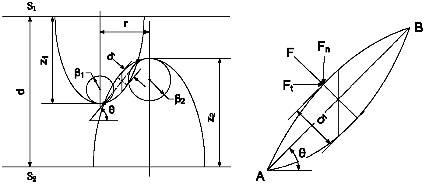
[0035] figure 1 It is the asperity contact force analysis diagram studied by the present invention. In the figure, S 1 , S 2 respectively represent two contact surfaces; d is the distance between two contact surfaces; z 1 ,z 2 are the heights of the contact asperities; β 1 , β 2 are the radius of curvature of the contact asperity peak; r is the distance between the symmetry axes of two asperities; θ is the contact angle; δ is the normal deformation of the contact area.

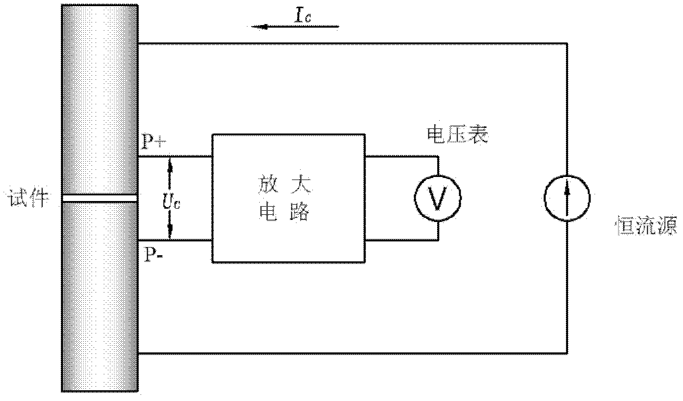
[0036] figure 2 The principle of measuring contact resistance for the four-point method. The method is to provide a constant current for the joint surface, measure the contact voltage of the joint surface, and obtain the contact resistance of the joint surface.

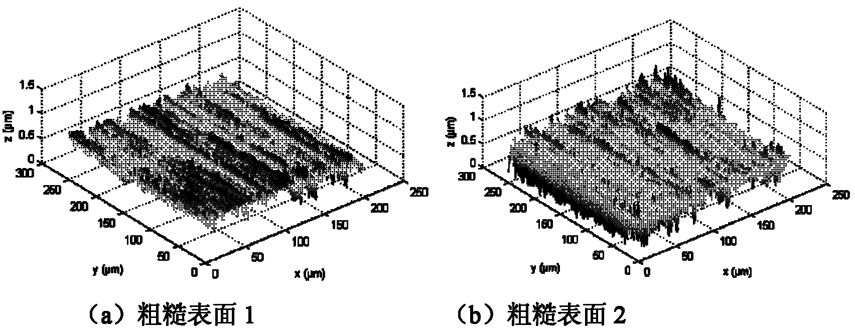
[0037] image 3 It is the microscopic surface morphology of the two rough surfaces of the bonding surface measured in the embodiment of the present invention, and the processing methods of the two rough surfaces are grinding.

[0038] Fig...


PUM

PropertyMeasurementUnit
elastic modulusaaaaaaaaaa
electrical conductivityaaaaaaaaaa
Poisson's ratioaaaaaaaaaa

Abstract

The invention provides a new method for indirectly obtaining normal contact stiffness of joint surface according to theoretical calculation and experimental test under the condition that the contact resistance ratio of the fixed joint surface is measured more easily than the normal contact stiffness. Relationship between joint surface contact resistance RC and normal contact stiffness Ktot is established by measurement and aftertreatment for micro appearance of contact surface. Firstly, an expression of the joint surface contact resistance RC is established; then the expression of normal contact stiffness Ktot is established; at the last, the relationship between the joint surface contact resistance RC and the normal contact stiffness Ktot is established. According to the invention, the method overcomes the defect that the normal contact stiffness is measured difficultly; the method considers elasto-plastic contact of two coarse surfaces, and further considers the more comprehensive, accurate actual surface appearance information.

Description

technical field [0001] The invention relates to a method for determining the normal contact stiffness of a fixed joint surface, in particular to a method for inverting the contact stiffness by testing the contact resistance based on the microscopic topography of two contact surfaces of the joint surface. Background technique [0002] There is a close relationship between the characteristics of the joint surface and the static and dynamic characteristics of the mechanical structure, as well as vibration and vibration control. Since the 1960s, scholars from various countries have studied the problems of the joint surface from the macro to the micro, from the phenomenon to the essence. A lot of research has been carried out. Due to the many factors affecting the characteristic parameters of the binding surface, its mechanism of action is complex and has strong nonlinear characteristics, and the nature of the mechanism of the binding surface has not yet been fully understood and...

Claims


Application Information

Patent Timeline
Patent Type & Authority Applications(China)
IPC IPC(8): G01N27/04
Inventor 李宝童洪军刘春青庄艳杜飞
Owner XI AN JIAOTONG UNIV
Why Eureka
Try Eureka