
Method for determining precision of blind-hole method residual stress testing system

A technology of residual stress and testing system, applied in the direction of measuring devices, force/torque/work measuring instruments, instruments, etc., can solve the problems of not being able to know the accuracy of measurement, and achieve high reliability, convenient material collection, and small residual stress Effect

Inactive Publication Date: 2012-07-25
SHOUGANG CORPORATION
View PDF2 Cites 27 Cited by
  • Summary
  • Abstract
  • Description
  • Claims
  • Application Information

AI Technical Summary

Problems solved by technology

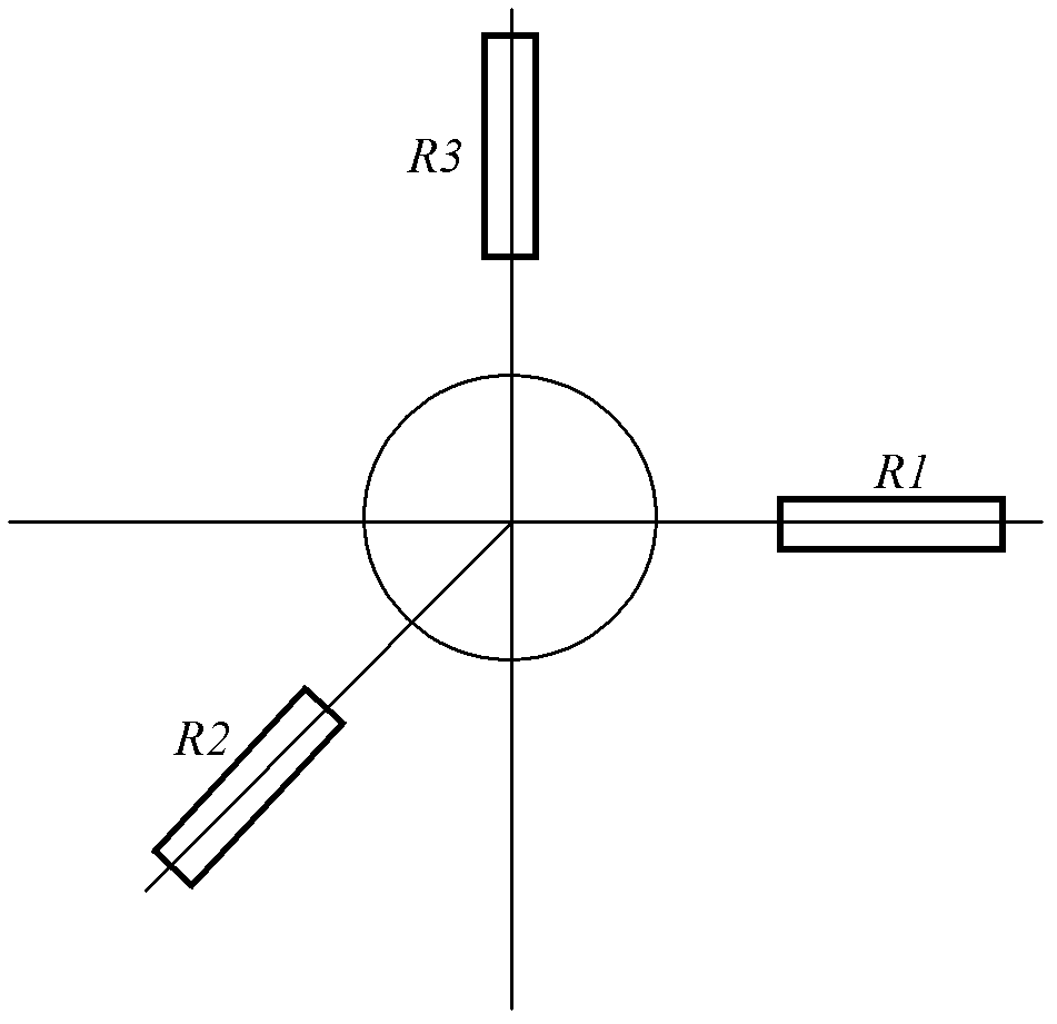
[0003] However, for the blind hole method to test the residual stress, due to its many influencing factors, the quality of the patch, the eccentricity of the drilling, and the additional strain all have an impact on the test results, especially when the electric drill is used for drilling. The additional strain generated in the process, drilling eccentricity and other influencing factors have a great impact on the test results. Compared with electric drilling, high-speed air drilling has much higher precision, but it is also impossible to know the accuracy of its measurement.
[0004] At present, there is no clear standard and method in the world to verify the accuracy of the residual stress test system of the blind hole method. The Chinese shipbuilding industry standard CB 3395 and the American Society for Testing and Materials standard ASTM E 837 are to reduce the experimental error. There are specific correction methods for deformation within a certain range, but no explanation is given on how to evaluate the accuracy of the entire blind hole method residual stress testing system

Method used


Image

  • Method for determining precision of blind-hole method residual stress testing system
  • Method for determining precision of blind-hole method residual stress testing system
  • Method for determining precision of blind-hole method residual stress testing system

Examples


Embodiment 1

[0024] A method for measuring the accuracy of a blind hole method residual stress testing system, comprising the following steps:

[0025] 1) Sample plate sampling: Take a piece of high-strength steel plate with a thickness of 8mm and a size of 400mm×200mm.

[0026] 2) Stress-relief annealing: In this embodiment, the furnace is slowly heated to 650° C., kept for 2 hours, and then cooled to room temperature with the furnace.

[0027] 3) Sample surface preparation and strain gauge attachment: Arrange 1 test point every 50 mm on the 400 mm long annealed plate, and arrange 7 test points in total; polish and clean the surface of the measuring point position, and then place the test point at the measuring point position Paste the strain gauges and cure for 18 hours.

[0028] 4) Linking of data lines: Use an electric soldering iron to weld the wires and strain gauge leads to the terminals, and then connect the wires to the strain recorder.

[0029] 5) Test parameter setting: Accord...


PUM


Abstract

The invention belongs to the technical field of precision determination, and relates to a method for determining the precision of a blind-hole method residual stress testing system. The method comprises the specific technologies of sample plate sampling, stress-relieving annealing, sample surface preparing and strain gauge adhering, data line connection, testing parameter configuring, hole drilling, data collecting, data processing, and precision determining. The method is advantaged in stable technology and accurate result. With the method, deviations of a testing system can be visually, rapidly, and quantitatively determined. Therefore, testing errors caused by influencing factors such as strain gauge quality, hole drilling eccentricity, and additional strain can be conveniently adjusted. Thus, the accuracy of the residual stress testing before and after hot rolled coil decoiling can be ensured.

Description

technical field [0001] The invention belongs to the technical field of precision measurement, and in particular relates to a method for measuring the precision of a blind hole method residual stress testing system. Background technique [0002] After the hot-rolled coil is flattened and cut to length, the phenomenon of "bow back" and "bow" often occurs. The reason is mainly caused by the introduction of residual stress due to the uneven plastic deformation of the upper and lower surfaces of the sheet metal (outer and inner surfaces of the coil) during the Kaiping process. Too much residual stress and its unreasonable distribution will cause the steel plate to be warped or twisted after mechanical / flame cutting at the user's site, making it unusable. By testing and analyzing the distribution law of residual stress of the coil before and after the flattening by the blind hole method, it can provide direct data support for the establishment of a relatively complete flattening ...

Claims


Application Information

Patent Timeline
IPC IPC(8): G01N27/04G01L5/00
Inventor 谭洪锋王萍杨雷刘卫平周晓伟
Owner SHOUGANG CORPORATION
Learn More