[0028] The specific embodiments of the present invention will be described in further detail below in conjunction with the drawings and embodiments. The following examples are used to illustrate the present invention, but not to limit the scope of the present invention.
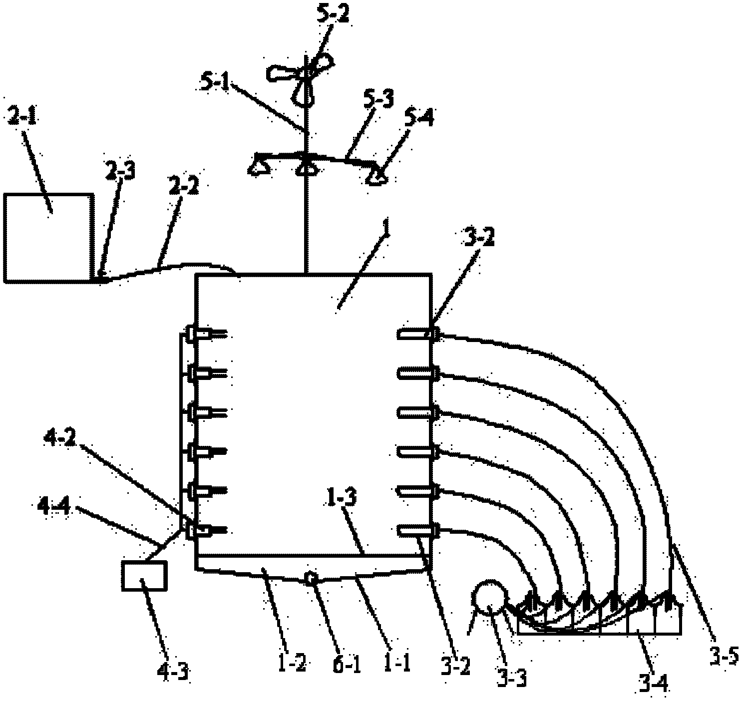
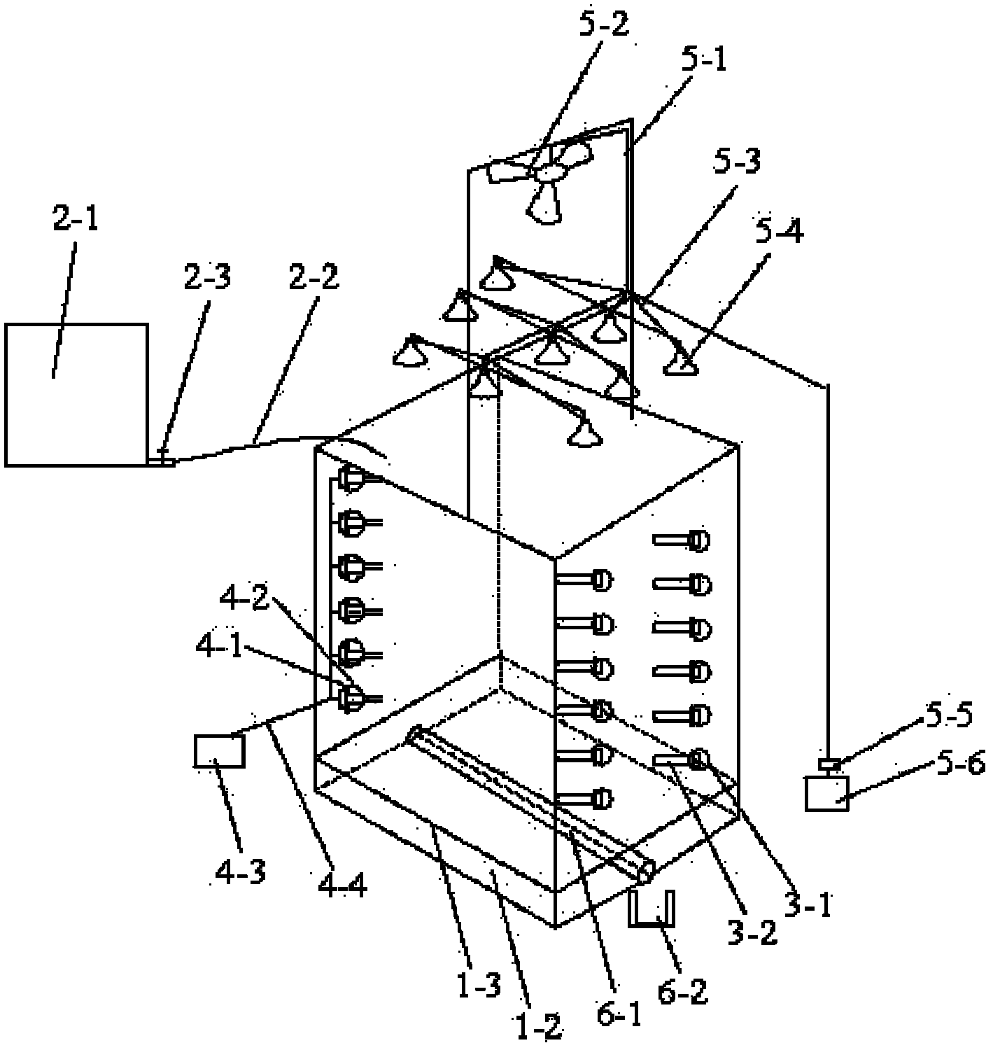
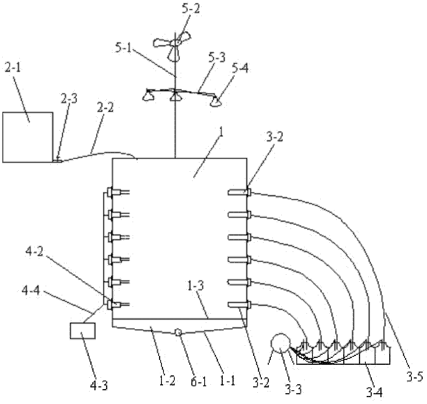
[0029] Such as figure 1 with figure 2 As shown, a simulated field soil solute transport system of the present invention includes a soil tank 1, a water supply system, a sampling system, a data collection system, and a leaching liquid collection system; the inner wall and bottom of the soil tank 1 are provided with a waterproof layer, and the soil The inside of the tank 1 is filled with soil; the water supply system is located outside of the soil tank 1 and supplies water to the soil tank 1 from top to bottom; the sampling system is installed on the side wall of the soil tank 1 to measure the soil contained in the soil tank 1. The data collection system is installed on the side wall of the soil tank 1 to monitor the water content of the soil at different depths in the soil tank 1 regularly; the eluent collection system is located at the bottom of the soil tank 1 to collect the soil tank 1 eluent.
[0030] The soil trench 1 can be made of clay and coated with cement on its four side walls. The size of the soil trench 1 can be: length 1.2m, width 1.2m, and height 1.5m. The inner wall and bottom of the soil trench 1 are respectively A waterproof layer is formed by coating with waterproof glue. The bottom of the soil tank 1 is a slope 1-1 with a slope of 5%. The bottom is provided with a filter layer 1-2 and a permeable cloth 1-3, and a permeable cloth 1-3. Located above the filter layer 1-2, the filter layer 1-2 is made of quartz sand, and the role of the filter layer is to prevent the leachate from carrying the soil out of the soil tank 1. After the installation of the filter layer 1-2 and the permeable cloth 1-3 is completed, the soil is filled into the soil trench 1 according to the bulk density of the actual field soil.
[0031] The water supply system includes a water tank 2-1. The water tank 2-1 supplies water to the soil tank 1 from top to bottom through a water supply pipe 2-2. One side of the water tank 2-1 is transparent, and the transparent part is marked with a volume scale. A water outlet valve 2-3 is provided at the junction of the water tank 2-1 and the water supply pipe 2-2. Fill the water tank 2-1 with reclaimed water, open the outlet valve 2-3, the reclaimed water in the water tank 2-1 will flow into the soil tank 1 through the water supply pipe 2-2, and close the outlet valve 2 when the filling amount is reached each time. 3 Then stop the water tank 2-1 filling the soil tank 1.
[0032] The sampling system includes a soil solution extractor 3-2, a vacuum pump 3-3, a sampling bottle 3-4, and a sampling port 3-1 opened on the side wall of the soil tank. 1 Different heights on the side walls, such as figure 2 , The sampling port 3-1 is divided into two vertical arrangements. The vacuum pump 3-3 and the sampling bottle 3-4 are not shown in the figure. The soil solution extractor 3-2 extracts the solution in the soil through the sampling port 3-1, and collects the extracted solution into the sampling bottle 3-4 through the sampling pipe 3-5, the vacuum pump 3-4 and the sampling pipe 3-5 Connect like figure 1 Shown. The negative pressure in the soil solution extractor 3-2 is increased to 0.06MPa~0.08MPa through the vacuum pump 3-4, so that the soil solution flows into the sampling bottle 3-4 through the sampling tube. After that, the solution sample can be tested according to the test needs. Chemical analysis in order to record the transformation of solutes in the soil.
[0033] The data acquisition system includes a soil moisture sensor 4-2, a data collector 4-3, and a sample port 4-1 opened on the sidewall of the soil tank. The sample port 4-1 is opened in another sample port 3-1. On one side wall, the sample testing port 4-1 has a plurality of different heights on the side wall of the soil tank 1, which can form a vertical arrangement, such as figure 2 Shown in. The soil moisture sensor 4-2 detects the soil through the sample port 4-1, and sends the detection signal to the data collector 4-3 through the data signal cable 4-4. The data acquisition system can periodically read and record the data of the sensors in order to observe and record the migration of solutes in the soil.
[0034] The eluent collection system includes a water collection pipe 6-1 and an eluent receiver 6-2. The water collection pipe 6-1 is set at the bottom of the soil tank 1, on a slope 1-1, and is sequentially covered with a filter layer 1- 2 and permeable cloth 1-3, the water collecting pipe 6-1 has a plurality of water collecting holes on the pipe wall facing the inside of the soil tank, the water collecting pipe 6-1 and the eluent receiver 6-2 arranged outside the soil tank connection. The function of the eluent collection system is to measure the volume of the eluent after each irrigation to before the next irrigation, so as to record the leaching of solutes in the soil, and the water in the eluent receiver 6-2 can be taken The samples were chemically analyzed to quantitatively calculate the solute balance of the test soil before and after irrigation.
[0035] Such as figure 2 The simulated field soil solute transport system also includes an evaporation system, which is arranged above the soil and used to evaporate the water contained in the soil in the soil tank. The evaporation system includes a first bracket 5-1, a fan 5-2, a distribution box 5-5, a controller 5-6, a second bracket 5-3, and an infrared lamp 5- installed on the second bracket 5-3 4. Among them, the first bracket 5-1 is erected above the soil trough 1, the fan 5-2 is hung on the first bracket 5-1, and the second bracket 5-3 is fixed on the first bracket 5-1 and is located at Below the fan 5-2; the fan 5-2 and the infrared lamp 5-4 are respectively connected to the distribution box 5-5 through wires, and the distribution box 5-5 is connected to the controller 5-6 through signal cables. In order to ensure that the light is evenly irradiated to the soil surface, multiple rows of second brackets 5-3 can be provided, and each row of second brackets 5-3 is provided with multiple infrared lamps 5-4.
[0036] The working process of a simulated field soil solute transport system provided by the above technical scheme is: first, the field soil in the required research area is air-dried and sieved, and then filled into the soil tank 1 with the actual field soil bulk density. The bottom of the soil front soil tank 1 has been equipped with a 10cm-thick filter layer 1-2, a permeable cloth 1-3, and a water collection pipe 6-1; after the soil is filled, fill the water tank 2-1 with reclaimed water and turn on the water outlet Valve 2-3, the water flows into the soil tank 1 through the water supply pipe, and closes the outlet valve 2-3 when the water volume reaches each time; the water content is detected by the soil moisture sensor 4-2, and the detection signal is connected via the data signal cable 4-4 Go to the data collector 4-3 to obtain the moisture content of each layer of soil during the soil moisture infiltration process; start the evaporation system on the second day after irrigation, the evaporation system will stop working after reaching a certain amount of evaporation every day, and pass the evaporation system When the water content of the soil surface after evaporation is 65% of the soil field water holding capacity, the vacuum pump 3-3 is used to increase the negative pressure in the soil solution extractor 3-2 to extract the soil solution; at the same time, the seepage liquid at the bottom of the soil tank passes through the collection pipe 6-1 Flow into the eluent receiver 6-2, measure the volume of the eluent after each irrigation and before the next irrigation, and take a water sample for chemical analysis. After the extraction of the soil solution is complete, perform the next irrigation and repeat the above steps.
[0037] For the impact of poor-quality water, rainfall, fertilization and other treatments on the soil, refer to the above test procedures.
[0038] The above are only the preferred embodiments of the present invention. It should be pointed out that for those of ordinary skill in the art, without departing from the technical principles of the present invention, several improvements and substitutions can be made. These improvements and substitutions It should also be regarded as the protection scope of the present invention.