Method for calibrating inherent wave power of iron core type permanent magnet synchronous linear motor

A permanent magnet synchronous linear and linear motor technology, used in electric components, electrical components, electromechanical devices, etc., can solve the problem of difficult to measure cogging force and magnetic resistance, system instability, affecting the position accuracy of the servo motion system, etc. question

Active Publication Date: 2014-01-29
TSINGHUA UNIV +1
View PDF2 Cites 0 Cited by
  • Summary
  • Abstract
  • Description
  • Claims
  • Application Information

AI Technical Summary

Problems solved by technology

The mathematical forms of the cogging force and the magnetic resistance are the sum of infinite Fourier series. It is not easy to measure the precise values ​​of the cogging force and the magnetic resistance through theoretical methods, and the cogging force also directly changes the magnetic resistance. The force directly affects the position accuracy of the servo motion system including the motor, and will cause speed fluctuations, mechanical structure vibrations, and even cause system instability

Method used


Image

  • Method for calibrating inherent wave power of iron core type permanent magnet synchronous linear motor
  • Method for calibrating inherent wave power of iron core type permanent magnet synchronous linear motor
  • Method for calibrating inherent wave power of iron core type permanent magnet synchronous linear motor

Examples


Embodiment Construction

[0043] The present invention will be further described below in conjunction with the accompanying drawings to the principle, structure and working process of the present invention.

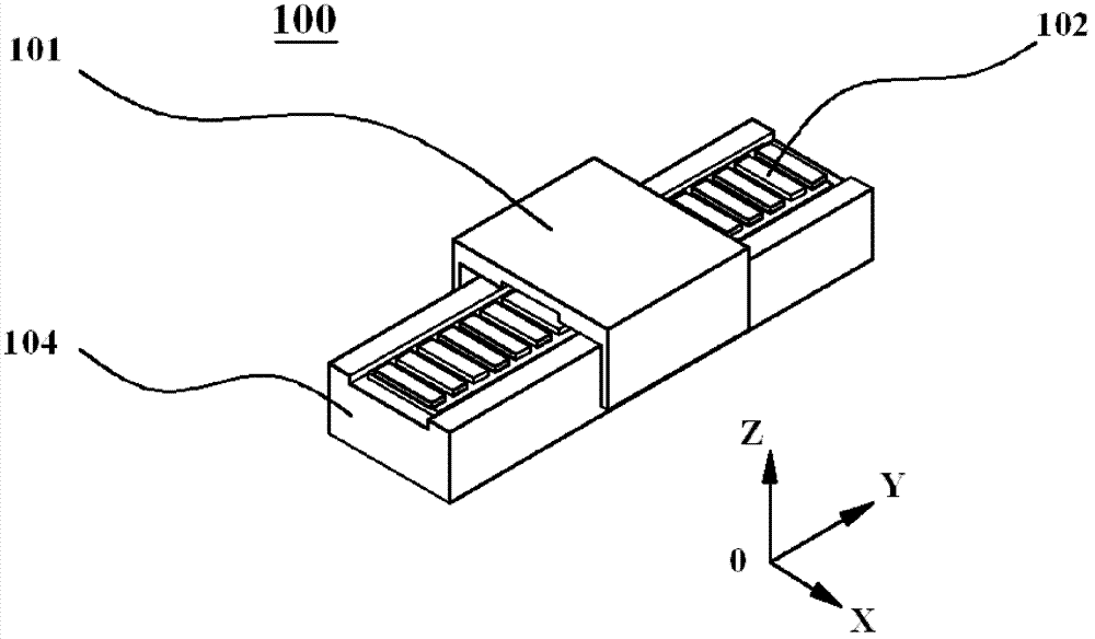
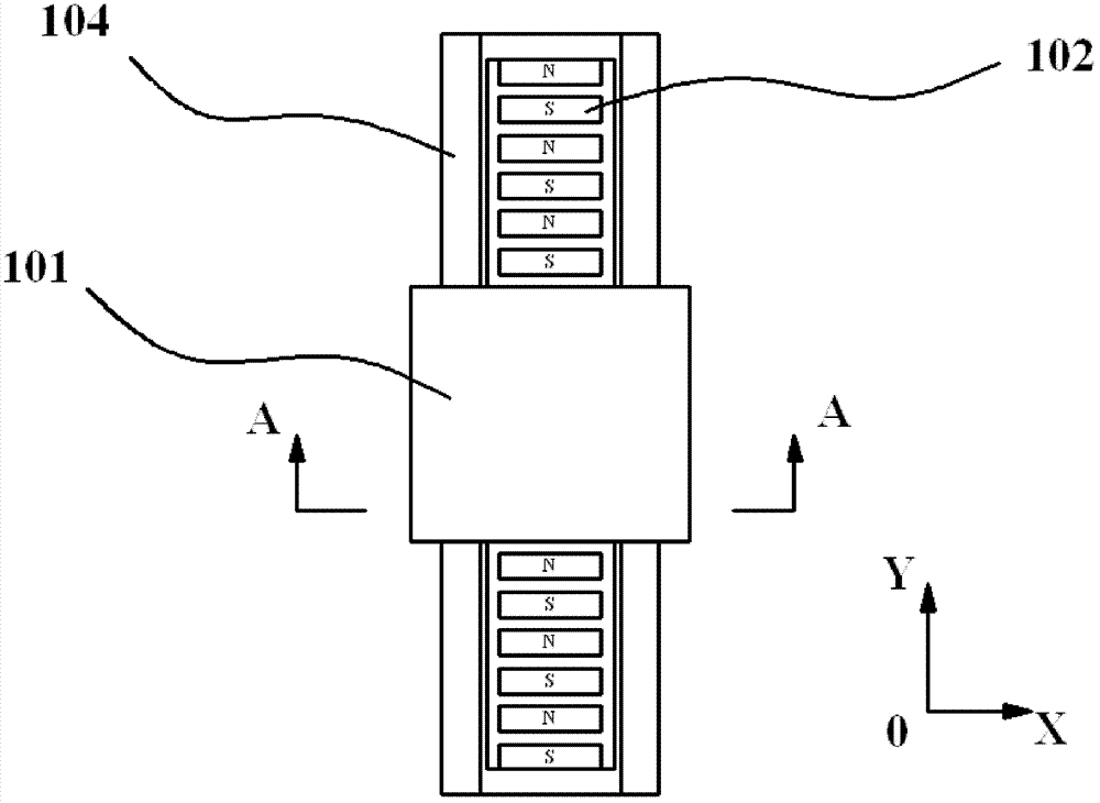
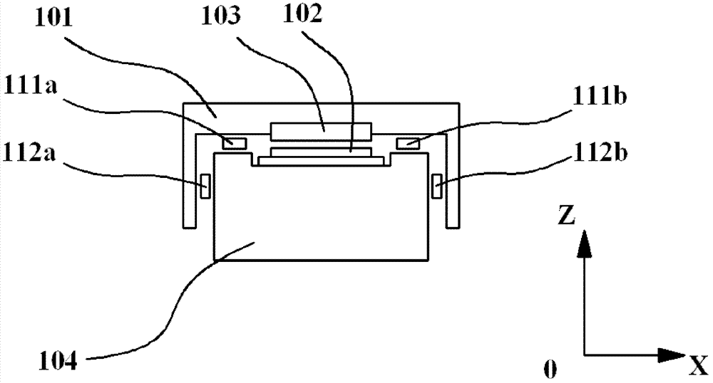
[0044] figure 1 It is a structural schematic diagram of an iron-core permanent magnet synchronous linear motor 100, figure 2 is the top view of the motor, image 3 It is a sectional view of the motor along plane A-A. The iron core type permanent magnet synchronous linear motor 100 includes a positioning element 101 , a permanent magnet 102 , a coil 103 and a base 104 . The positioning element 101 is supported by the first air bearing support 111a and the second air bearing support 111b along the Z axis direction, and the positioning element 101 is supported by the third air bearing support 112a and the fourth air bearing support 112b along the X axis direction. The permanent magnets 102 are arranged in a Halbach array. The coil 103 is the mover of the linear motor 100 , and will generate a Lo...


PUM


Abstract

The invention discloses a method for calibrating an inherent wave power of an iron core type permanent magnet synchronous linear motor. The iron core type permanent magnet synchronous linear motor has two inherent cogging force and detent force, the cogging force is only related to a relative position between a rotor and a stator of a motor, and the detent force is related to the relative position between the rotor and the stator of the motor and a winding current. According to the invention, the method for calibrating the cogging force and the detent force is given through two groups of experiments. In the first group of experiments, a track of the rotor of the motor, which moves from a D1 point to a D2 point along the positive direction of a movement axis, is given, and the uniform motion of the rotor of the motor along the positive direction of the movement axis is completed according to the given track. In the second group of experiments, an external force with constant size along the direction of the movement axis is applied to the rotor of the motor, and the uniform motion of the rotor of the motor along the positive direction of the movement axis is completed according to the track given in the first group of experiments, and acting forces output by a controller in the two groups of experiments are respectively recorded. The method for calibrating the inherent wave power of the iron core type permanent magnet synchronous linear motor is given according to a force balance condition.

Description

technical field [0001] The invention relates to a method for calibrating the inherent wave force caused by the structure of an iron-core permanent magnet synchronous linear motor. Background technique [0002] Iron-core permanent magnet synchronous linear motor is an electromagnetic device that directly converts electromagnetic energy into linear motion mechanical energy. It has the advantages of simple structure, high positioning accuracy, and fast response speed. It is widely used in CNC machine tools, semiconductor processing equipment, etc. The field of modern precision manufacturing. [0003] The structure of the iron-core permanent magnet synchronous linear motor produces complex nonlinear wave force. The inherent wave force includes two components: cogging force and magnetic resistance, in which the cogging force is only related to the motor's mover and The relative position between the stators is related, and there is a certain cogging force in each relative positio...

Claims


Application Information

Patent Timeline
Patent Type & Authority Patents(China)
IPC IPC(8): H02K41/03G01L5/00
Inventor 穆海华朱煜李鑫杨开明尹文生张鸣徐登峰
Owner TSINGHUA UNIV
Why Eureka
Try Eureka