Method for reducing power consumption of integrated circuit system of Ethernet passive optical network physical layer
A passive optical network and integrated circuit technology, applied in the selection device of multiplexing system, transmission system, digital transmission system, etc., can solve the problems of delay, difficult operation, poor flexibility, etc., and reduce peak power consumption , reduce peak power consumption, achieve simple effect
- Summary
- Abstract
- Description
- Claims
- Application Information
AI Technical Summary
Problems solved by technology
Method used
Image
Examples
specific Embodiment approach 1
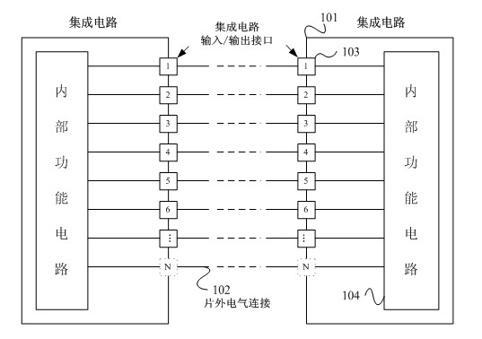
[0104] figure 1 Among them, "integrated circuit 101" refers to an integrated circuit that is applied in the physical layer circuit system of an Ethernet device, has certain functional unit properties, and is packaged as a certain circuit element, such as a processor chip, a memory chip, and the like. Its implementation can be a field programmable gate array or a fully customized ASIC.
[0105] figure 1 In , "off-chip electrical connection 102" refers to the circuit connection between integrated circuits and integrated circuits, generally in the form of metal wiring on a printed circuit board.
[0106] figure 1 In , the "input and output interface 103" marked by 1-N refers to a group of I / O ports used to transmit parallel data in the integrated circuit. Generally used to transmit high / low level digital logic signals. The internal functional circuit needs to input (or output) the parallel digital logic signal, which will be input (or output to the electrical connection line ...
specific Embodiment approach 2
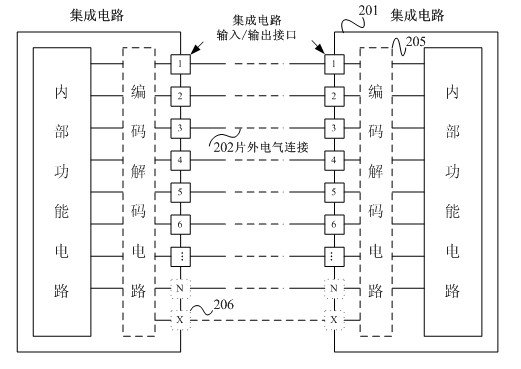
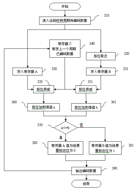
[0135] The second embodiment is mainly to adjust and improve the detailed workflow of the codec device and the codec method adopted.
[0136] Because in some cases, if the encoding scheme of the first embodiment is adopted, the effect of reducing I / O unit flipping may decrease with the increase of the parallel I / O bit width. Especially when transmitting some specific data types (such as floating-point data with only a small change in part of the mantissa in the two cycles before and after the transmission). Therefore, the second embodiment proposes an improved method to split the data to be encoded into multiple segments. Depending on the type of binary parallel data to be transmitted, multiple segments can be encoded separately, or only some of the sub-segments can be encoded.
[0137] The flowchart of the encoding method is as follows Figure 5 shown.
[0138] Step 510: first read in the data to be encoded in the current clock cycle;
[0139] Step 520: Split the data int...
Embodiment approach 3
[0152] The difference between Embodiment 3 and Embodiment 1 is that due to the adjustment and improvement of the workflow of the encoding and decoding device and the adopted encoding and decoding methods, the encoding process will not generate flag bits that require additional I / O port transmission, thus Saves the number of I / O ports.
[0153] Since the third embodiment does not add an additional integrated circuit I / O port or an additional off-chip electrical connection, when it is applied to the physical layer circuit system of an Ethernet device, the existing printed circuit board, the direct electrical connection of the integrated circuit, etc. No modifications are required.
[0154] The encoding method flow is as follows Figure 7 shown.
[0155] Now take an 8-bit wide I / O bus as an example:
[0156] Step 700: setting a counter and checking the value of counter N;
[0157] Step 710: judge whether the value of the counter N is 7;
[0158] Step 720: If N is not 7, read...
PUM
 Abstract
Description
Claims
Application Information
 - R&D
- Intellectual Property
- Life Sciences
- Materials
- Tech Scout
- Unparalleled Data Quality
- Higher Quality Content
- 60% Fewer Hallucinations
Browse by: Latest US Patents, China's latest patents, Technical Efficacy Thesaurus, Application Domain, Technology Topic, Popular Technical Reports.
© 2025 PatSnap. All rights reserved.Legal|Privacy policy|Modern Slavery Act Transparency Statement|Sitemap|About US| Contact US: help@patsnap.com


