Novel powder selecting machine capable of uniformly scattering material

A powder classifier and uniform technology, applied in the direction of solid separation, separating solids from solids with airflow, chemical instruments and methods, etc., can solve problems such as easy to run rough, run rough, affect powder dispersion, etc., to achieve increased Large throwing area, increased spreading effect, and improved grading effect

Inactive Publication Date: 2012-08-01
JIANGSU A BITION ENVIRONMENTAL EQUIP
View PDF5 Cites 7 Cited by
  • Summary
  • Abstract
  • Description
  • Claims
  • Application Information

AI Technical Summary

Problems solved by technology

Theoretically, the material should be thrown into a 360-degree uniform material curtain by the powder separator, but as the capacity of the equipment increases, the number of feed ports of the powder separator is limited. The increase in the width of the disc ring is not proportional to the increase in the amount of material to be processed, and the processing capacity per unit area gradually increases. Even if the feed port of the powder classifier is increased to four, the material is still easily not fully scattered near the feed port. Sliding into clumps into the graded flow field
Although the existing powder classifier has made some improvements to the annular spreading disc, such as changing the radial corrugation to a spiral corrugation, increasing the throwing area; adding a rib to the outer edge of the spreading disc to delay the material sliding out time, The throwing area is increased, but the following problems still exist in this ring-shaped material spreading device: First, thicker material curtains and material-free cavities appear alternately around the grading cage, which not only causes the separation wind speed in the vortex field to be uneven, Inhomogeneous airflow velo

Method used


Image

  • Novel powder selecting machine capable of uniformly scattering material
  • Novel powder selecting machine capable of uniformly scattering material
  • Novel powder selecting machine capable of uniformly scattering material

Examples


Embodiment Construction

[0016] The present invention will be further described below in conjunction with the accompanying drawings and embodiments.

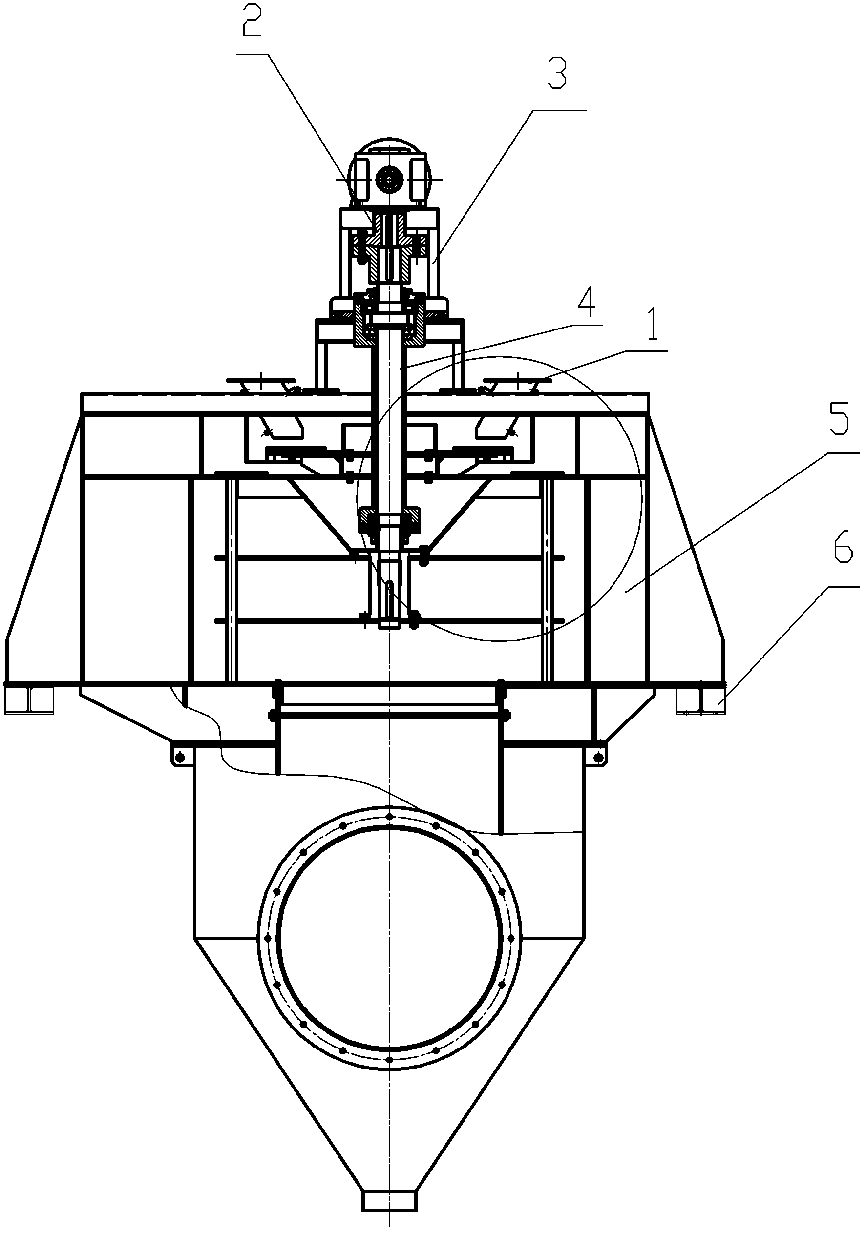
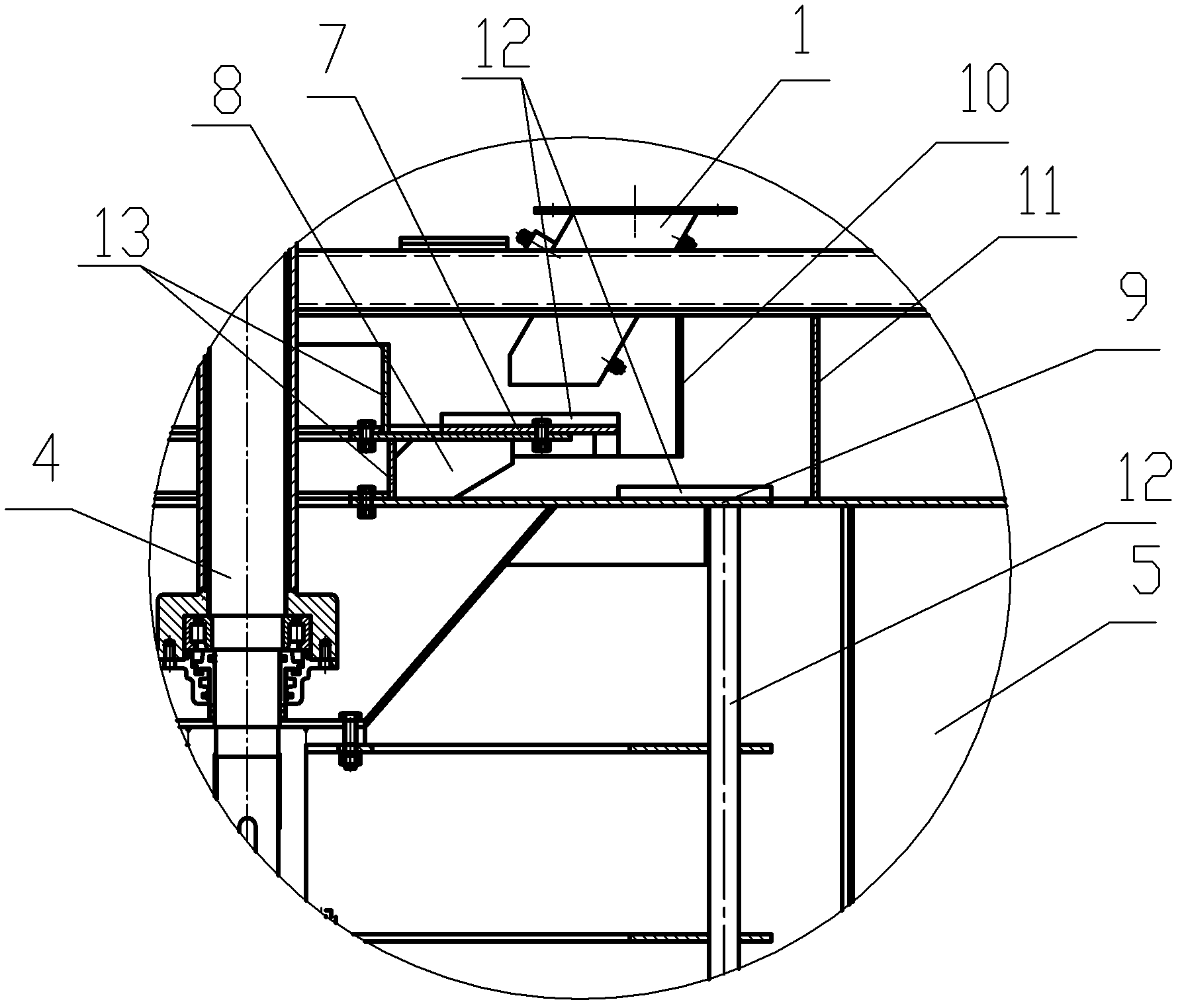
[0017] to combine figure 1 and figure 2 As shown, the novel classifier for evenly spreading materials in this embodiment includes a cylindrical housing 5, a support 6 for supporting the housing, a motor, a reducer, a shaft coupling 2, a frame 3, and a The rotating parts in the body, the motor drives the rotating parts to rotate through the reducer and the coupling. Described revolving part comprises rotating shaft 4, rotor 12, and the top of rotor 12 is fixedly provided with annular material spreading plate, and this material spreading plate is double-layer and comprises top layer material spreading plate 7 and bottom layer material spreading plate 9, top layer material spreading plate The disk 7 is set under the feed port 1 of the powder classifier, and a ring-shaped primary buffer plate 10 is arranged on the outer edge of the top layer of material ...


PUM


Abstract

The invention discloses a novel powder selecting machine capable of uniformly scattering a material, which comprises a cylindrical shell, a support base used for supporting the shell, a motor, a speed reducer, a coupling device, a rack and a rotating part arranged in the shell, wherein the rotating part comprises a spindle and a rotor, and an annular material scattering plate is fixedly arranged at the top of the rotor; the material scattering plate is provided with two layers, and comprises a top-layer material scattering plate and a bottom-layer material scattering plate, and the top-layer material scattering plate is arranged under a material inlet of the powder selecting machine; and an annular first-stage baffle plate is arranged correspondingly to the outer edge of the top-layer material scattering plate, the bottom-layer material scattering plate, the diameter of which is larger than the diameter of the top-layer material scattering plate, is arranged under the top-layer material scattering plate, an annular second-stage baffle plate is arranged correspondingly to the outer edge of the bottom-layer material scattering plate, the first-stage baffle plate and the second-stage baffle plate are both fixedly connected with the shell, the lower part of the first-stage baffle plate is corresponding to the plate surface of the bottom-layer material scattering plate, and the lower part of the second-stage baffle plate is corresponding to a material grading zone of the powder selecting machine. The powder selecting machine disclosed by the invention can make the material uniformly and loosely enter into the material grading zone, and enhance the grading precision of the material.

Description

technical field [0001] The invention relates to a grinding system equipment of an industrial enterprise, in particular to a new type of powder classifier which spreads materials evenly. Background technique [0002] The powder classifier is the material classification equipment for the grinding system of industrial enterprises. When the powder classifier is working, the materials to be classified are introduced from the feeding port, are hit and dispersed on the spreading plate, and then fly outward along the surrounding of the spreading plate, and then After the buffer plate collides, it falls into the powder selection chamber, where it meets the horizontal vortex airflow. Under the joint action of the guide vane and the rotor, the centrifugal force, the suction force of the air flow and the gravity act on the materials together to achieve classification. [0003] However, with the large-scale of grinding equipment, there are great defects in the structure of existing powde...

Claims


Application Information

Patent Timeline
IPC IPC(8): B07B7/083B07B11/02
Inventor 左其武张连中周峰
Owner JIANGSU A BITION ENVIRONMENTAL EQUIP
Why Eureka
Try Eureka