
Automatic tool changing mechanism with manipulator

A technology of automatic tool change and manipulator, applied in the direction of metal processing machinery parts, clamping, support, etc., can solve the problems of inapplicability to various machining centers, mechanism damage, inapplicability of various spindles, etc., to overcome the failure of tool release Effect

Inactive Publication Date: 2012-08-01
邵文远
View PDF7 Cites 0 Cited by
  • Summary
  • Abstract
  • Description
  • Claims
  • Application Information

AI Technical Summary

Problems solved by technology

[0003] The purpose of the present invention is to provide a new hydraulic cam-hydraulic linkage tool change mechanism to overcome the hidden dangers of tool release failure and mechanism damage in the prior art that may be caused by a small amount of oil leakage or temperature change, and that it cannot be applied to various spindles , can not be applied to the shortcomings of a variety of machining centers

Method used


Image

  • Automatic tool changing mechanism with manipulator
  • Automatic tool changing mechanism with manipulator
  • Automatic tool changing mechanism with manipulator

Examples


Embodiment Construction

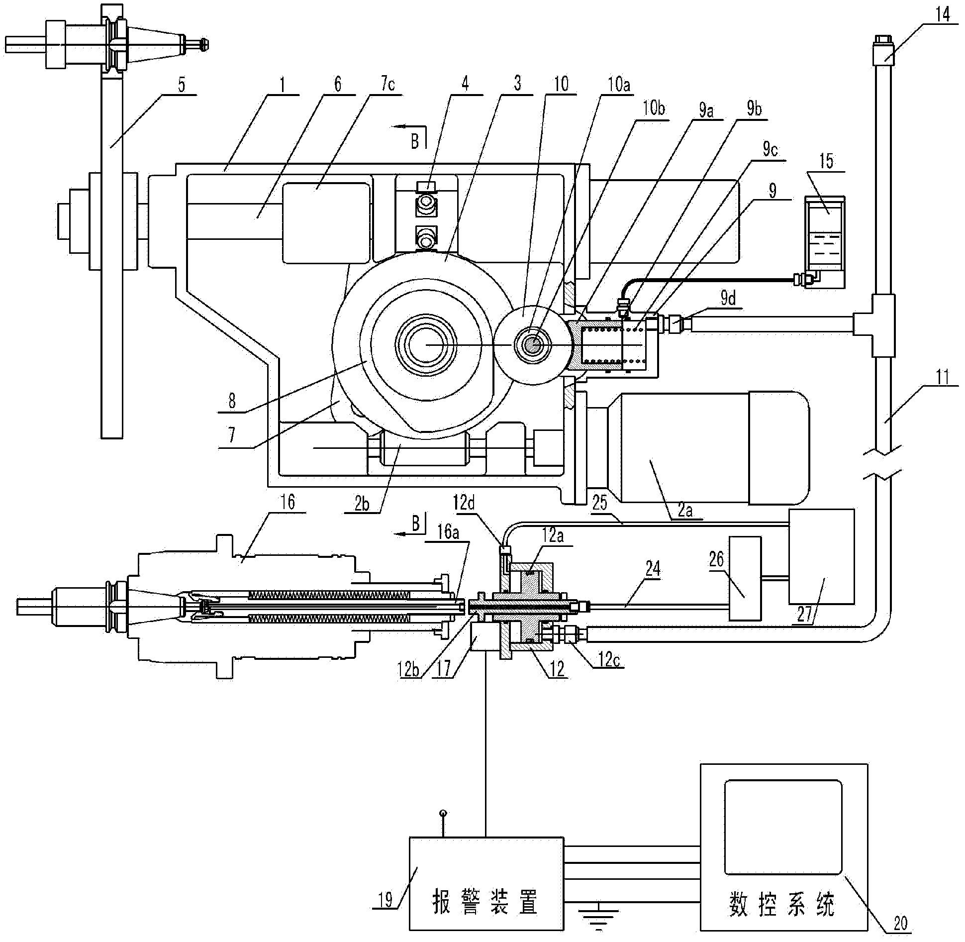
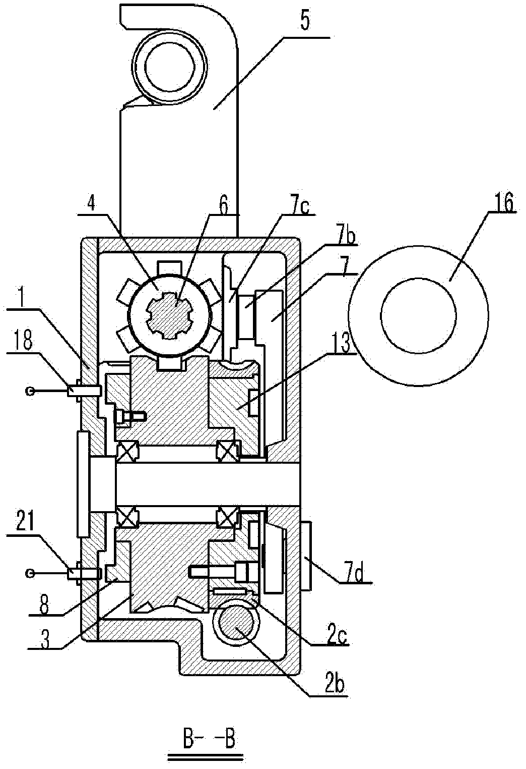
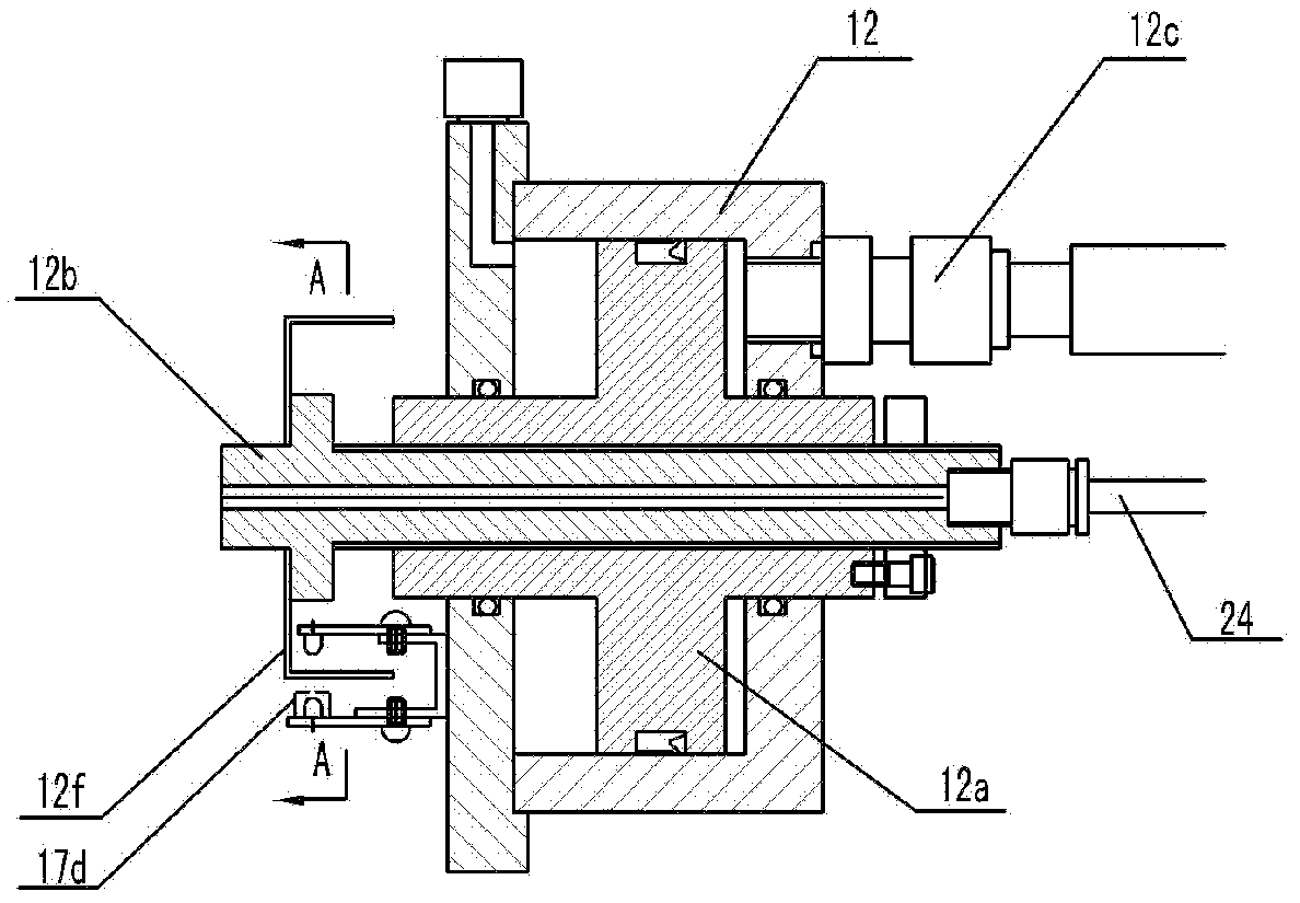
[0034] ginseng figure 1 and Figure 1a, the manipulator automatic tool change mechanism in this embodiment is composed of housing 1, brake motor 2a, reduction mechanism input shaft 2b, reduction mechanism output part 2c, swing arm cam 3, six-star wheel 4, manipulator 5, manipulator shaft 6, plug Knife lever 7, connecting rod 7b, bearing slider 7c, knife release cam 8, plunger oil pump 9, roller 10, high-pressure hose 11, knife release cylinder 12, spindle 16 with knife release bar 16a and numerical control system 20, etc. , the swing arm cam 3 is fixedly connected with the output worm wheel of the reduction mechanism 2, the annular cam groove on the outer circle of the swing arm cam 3 meshes with the six star wheel 4, and the plane insertion and extraction knife cam 13 on the end face of the swing arm cam 3 is connected with the insertion The roller on the knife-drawing lever 7 engages and passes through the lever 7 connecting rod 7b, and the bearing slider 7c pushes the mani...


PUM


Abstract

The invention discloses an automatic tool changing mechanism with a manipulator. The automatic tool changing mechanism comprises a shell, a brake motor, an input shaft of a speed reducing mechanism, an output component of the speed reducing mechanism, a swivel arm cam, a six-star wheel, the manipulator, a manipulator shaft, a tool inserting and pulling lever, a tool releasing cam, a plunger oil pump with a plunger, a roller wheel and a cam position switch and is characterized in that a cylinder body of the oil pump is provided with an reoiling hole communicated with a reoiling cup filled with oil; and a plunger return spring is arranged between the cylinder body of the oil pump and the plunger. The automatic tool changing mechanism disclosed by the invention can be used for eliminating hidden dangers of tool releasing fault and mechanism damage caused by trace oil leakage or temperature variation, and can be applicable to various main shafts and various processing centers.

Description

technical field [0001] The invention relates to an automatic tool-changing mechanism for a manipulator in a machining center, in particular to an automatic tool-changing mechanism for a manipulator that utilizes a cam to realize the coordinated control of the manipulator and the spindle loosening the tool during the automatic tool change process, and belongs to the technical field of metal cutting machine tools. Background technique [0002] Invention patent 200810011687.3-"Hydraulic cam linkage tool change mechanism of machining center" proposes a manipulator automatic tool change mechanism different from the traditional technology. According to the traditional technology, the tool changer manipulator only undertakes the actions of turning the tool back and inserting the tool. During this process, it needs to cooperate with the spindle loosening and broaching mechanism. The two mechanisms need to be detected and coordinated by the CNC system. The manipulator needs to be sta...

Claims


Application Information

Patent Timeline
Patent Type & Authority Applications(China)
IPC IPC(8): B23Q3/157
Inventor 邵文远
Owner 邵文远
Learn More