Eureka AIR delivers breakthrough ideas for toughest innovation challenges, trusted by R&D personnel around the world.

Rotational moulding machine

A molding machine and heating chamber technology, which is applied in the direction of coating, hollow objects, household appliances, etc., can solve the problem that the mold cannot be effectively guaranteed to be heated quickly and evenly, and the quality accuracy of the product surface texture is not high, and it is difficult to realize the mold heating and other problems to achieve the effect of ensuring rapid heating, compact structure and easy improvement

Active Publication Date: 2012-08-01
BEIJING UNIV OF CHEM TECH
View PDF3 Cites 14 Cited by
  • Summary
  • Abstract
  • Description
  • Claims
  • Application Information

AI Technical Summary

Problems solved by technology

The current rotomolding machines are almost all open structures, that is, the mechanical arm of the rotomolding machine is set outside the heating chamber. When the rotomolding machine is heating, the side door cannot be completely closed, leaving a large gap, because the mechanical arm needs to To bear heavy loads, it is necessary to design a larger size and space to meet the working needs; and the air duct and the heating chamber adopt a separate design, that is, the air duct is set outside the heating chamber. This structure causes a large part of heat loss. Causes long processing time cycle, low production efficiency and high energy consumption
In addition, after the existing rotomolding machine is manufactured, the structure and position of the mold frame and heating chamber are fixed and cannot be adjusted. When processing products of different sizes and shapes, especially products with complex shapes, the surface structure of the mold is complex. It is difficult to realize that each surface of the mold is heated in the center of the heating chamber, and it cannot effectively ensure that the mold is heated quickly and evenly, so the material is difficult to disperse evenly, and the quality precision of the processed product internal structure and surface texture is not high

Method used


Image

  • Rotational moulding machine
  • Rotational moulding machine
  • Rotational moulding machine

Examples


Embodiment Construction

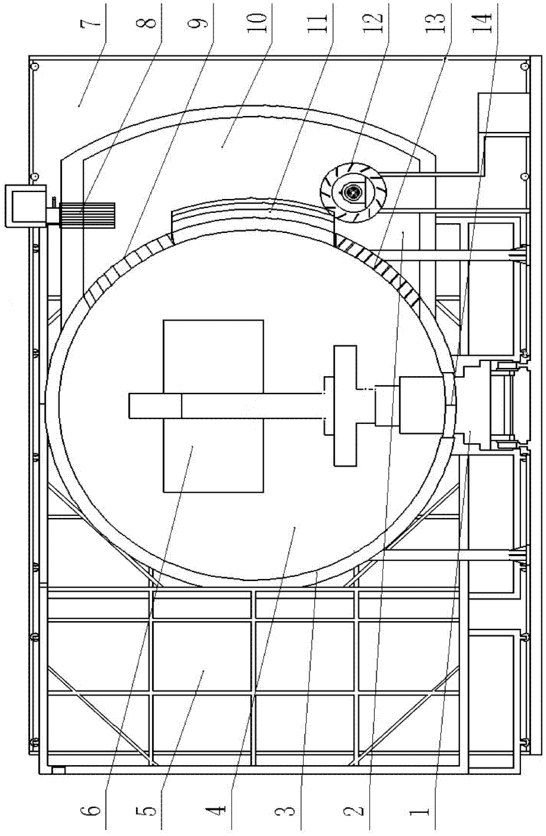
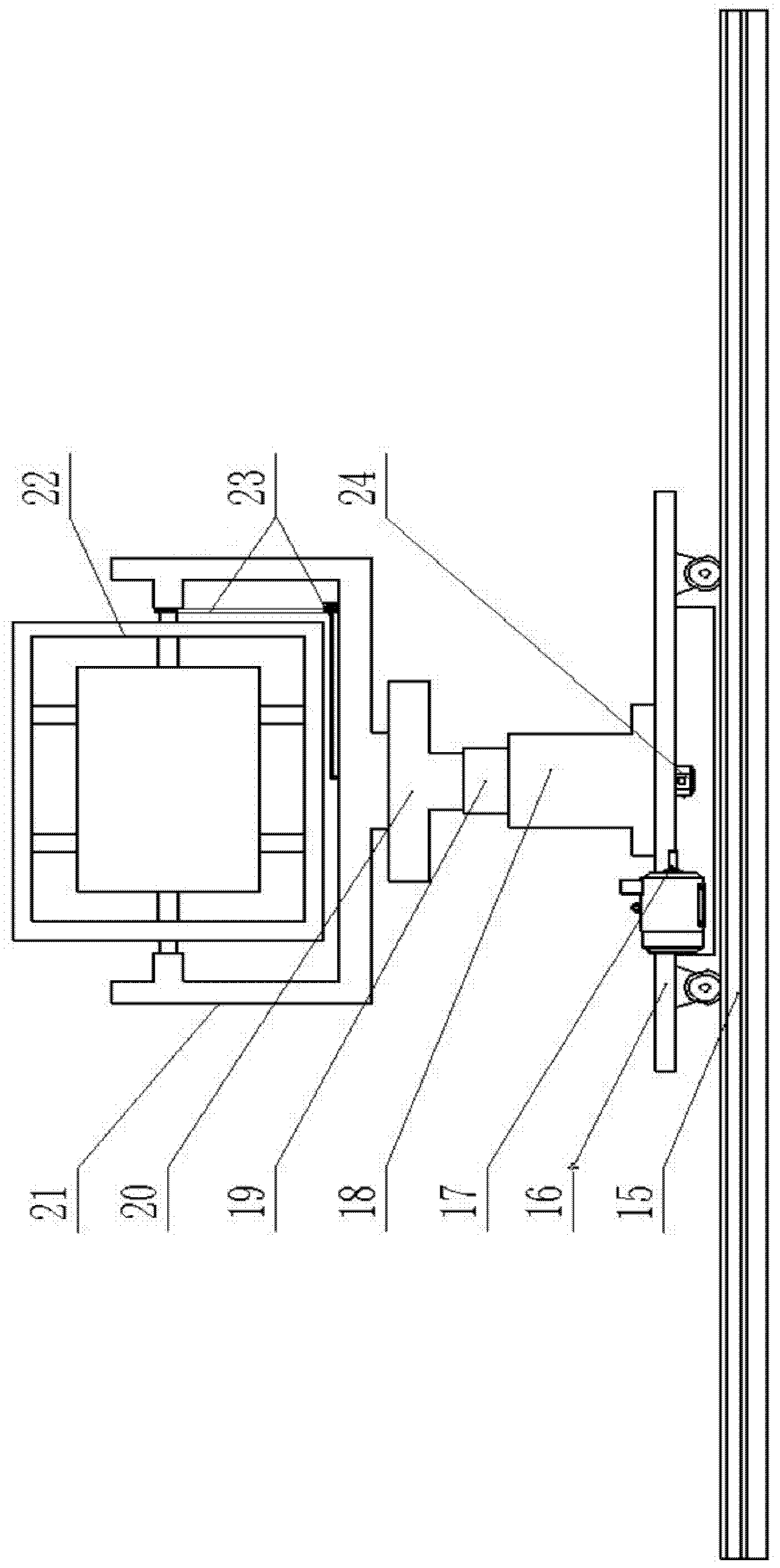
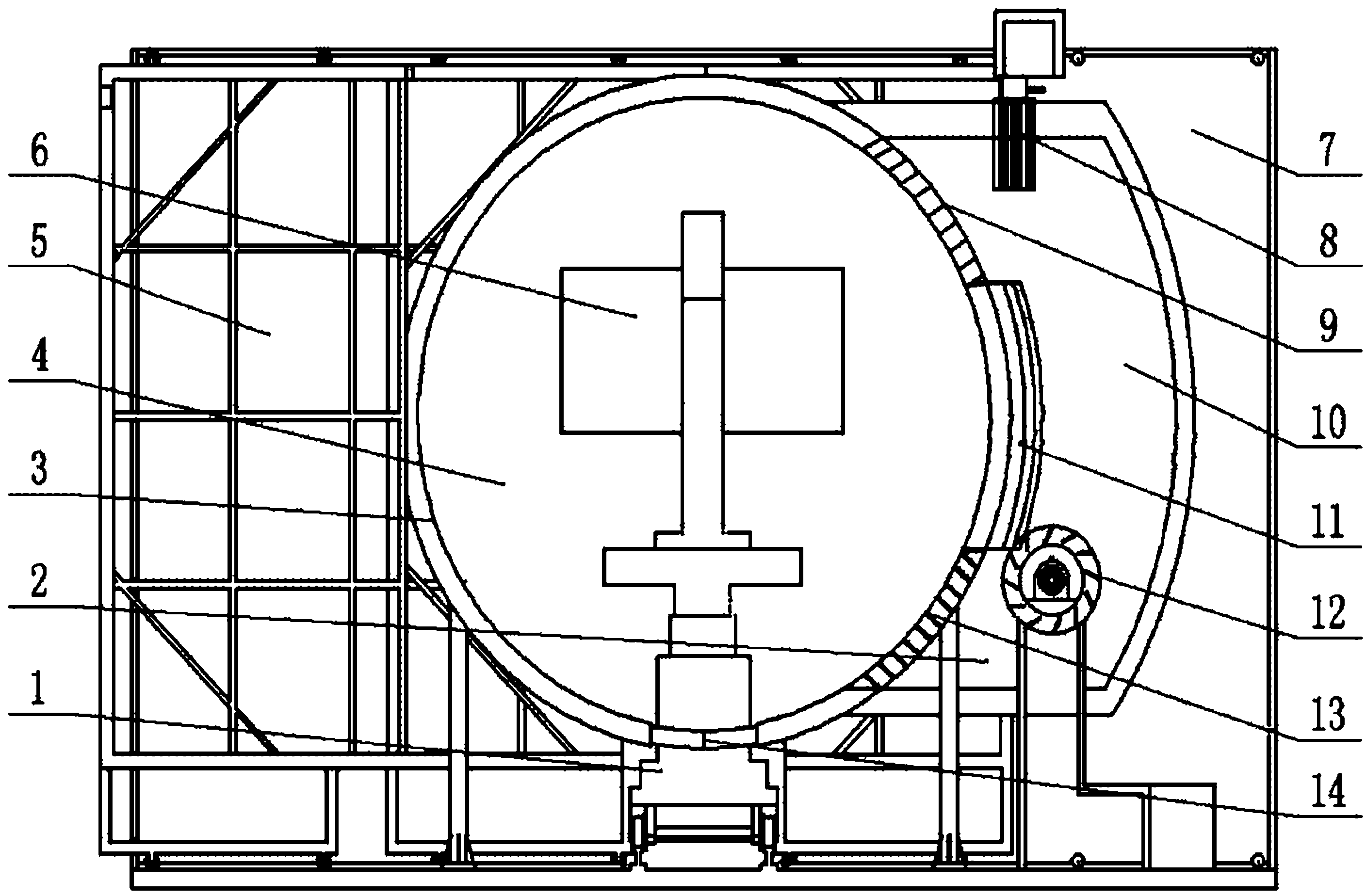
[0014] A kind of rotational molding machine of the present invention, as figure 1 with figure 2 As shown, it mainly includes a support system 1, a heating system 2, a heating chamber 4, and a track 15. The heating chamber 4 is surrounded by an oven wall 3, a front side door 5, a rear side door 7, and a bottom baffle 14. Located at the bottom of the oven wall 3, when the bracket system 1 moves into the heating chamber 4, it blocks the bottom opening of the oven wall 3, and the front side door 5 and the rear side door 7 can be opened to facilitate the bracket system 1 to move in and out of the heating chamber 4. The bracket system 1 includes Vehicle frame 16, driving motor 17, lifting column one 18, lifting column two 19, rotating disk 20, mold frame one 21, mold frame two 22, transmission shaft 23, rotating motor 24, mold 6 is installed on the mold frame two 22, Die frame two 22 is installed on mold frame one 21, and mold frame one is installed on the rotating disc 20. The ro...


PUM


Abstract

The invention relates to a rotational moulding machine which mainly comprises a bracket system, a heating system, a heating chamber and a rail, wherein the heating system is adjacent to the heating chamber and is composed of an oven wall, a front lateral door, a rear lateral door and a bottom baffle; a mould and a driving system for driving the mould to rotate around double shaft are arranged in the bracket system; the height of the mould is adjustable; the heating system is arranged on the side wall of the oven wall and comprises a combustion engine, an air inlet, an air flue, a circulating fan and an air outlet; and the air flue and the heating chamber are integral. On the basis of the integrated design of arranging the freely moving bracket system, fully sealing the periphery of the heating chamber and arranging the air flue with the heating chamber, the heat loss is reduced, the molding efficiency is increased, the energy consumption is reduced, and an independent bottom rotating mechanism is strong in bearing capacity. The working position of the mould is adjusted according to the size and quantity of the mould. A heat conducting chip is arranged between the air inlet and air outlet of the heating chamber, so that the quick heating and uniform heating of the mould are efficiently ensured and the total heat conveyed by the heating chamber is increased.

Description

technical field [0001] The invention relates to the technical field of rotomolding, in particular to a fully enclosed rotomolding machine with a rotary chassis, which is suitable for processing and manufacturing plastic products with large and extra-large sizes and complex structural shapes. Background technique [0002] The rotational molding machine is suitable for processing large-sized hollow products, so the rotational molding equipment itself is a large-scale mechanical equipment. The current rotomolding machines are almost all open structures, that is, the mechanical arm of the rotomolding machine is set outside the heating chamber. When the rotomolding machine is heating, the side door cannot be completely closed, leaving a large gap, because the mechanical arm needs to To bear heavy loads, it is necessary to design a larger size and space to meet the working needs; and the air duct and the heating chamber adopt a separate design, that is, the air duct is set outside...

Claims


Application Information

Patent Timeline
Patent Type & Authority Applications(China)
IPC IPC(8): B29C41/06B29C41/46B29C41/34B29L22/00
Inventor 杨卫民秦柳丁玉梅
Owner BEIJING UNIV OF CHEM TECH
Why Eureka
Eureka Blog
Learn More