Blade structure for centrifugal fans

A technology of blade structure and centrifugal fan, which is applied in the direction of mechanical equipment, machine/engine, liquid fuel engine, etc., can solve the problems of failure to achieve, affect the efficiency of the fan, and the installation angle destroys the uniform arrangement of the circumferential angle of the blade, so as to reduce the The effect of airflow resistance

Inactive Publication Date: 2012-08-01
GUANGDONG CHIGO AIR CONDITIONING +2
View PDF6 Cites 4 Cited by
  • Summary
  • Abstract
  • Description
  • Claims
  • Application Information

AI Technical Summary

Problems solved by technology

This will not only affect the efficiency of the fan, but also generate relatively large vibration and noise.
Although the performance of the multi-blade centrifugal fan is now optimized, it is mainly improved fr

Method used


Image

  • Blade structure for centrifugal fans
  • Blade structure for centrifugal fans
  • Blade structure for centrifugal fans

Examples


Embodiment 1

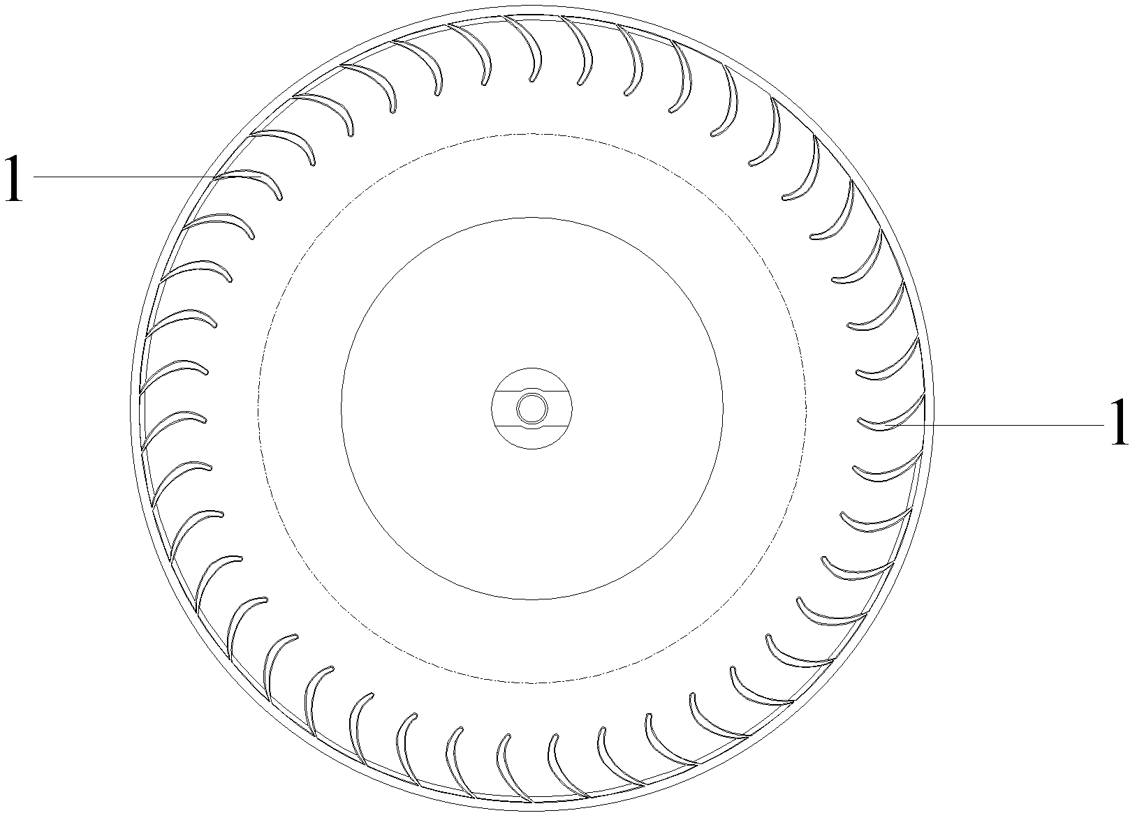
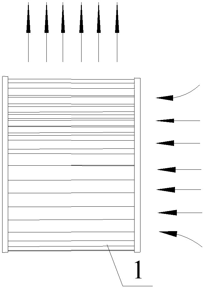
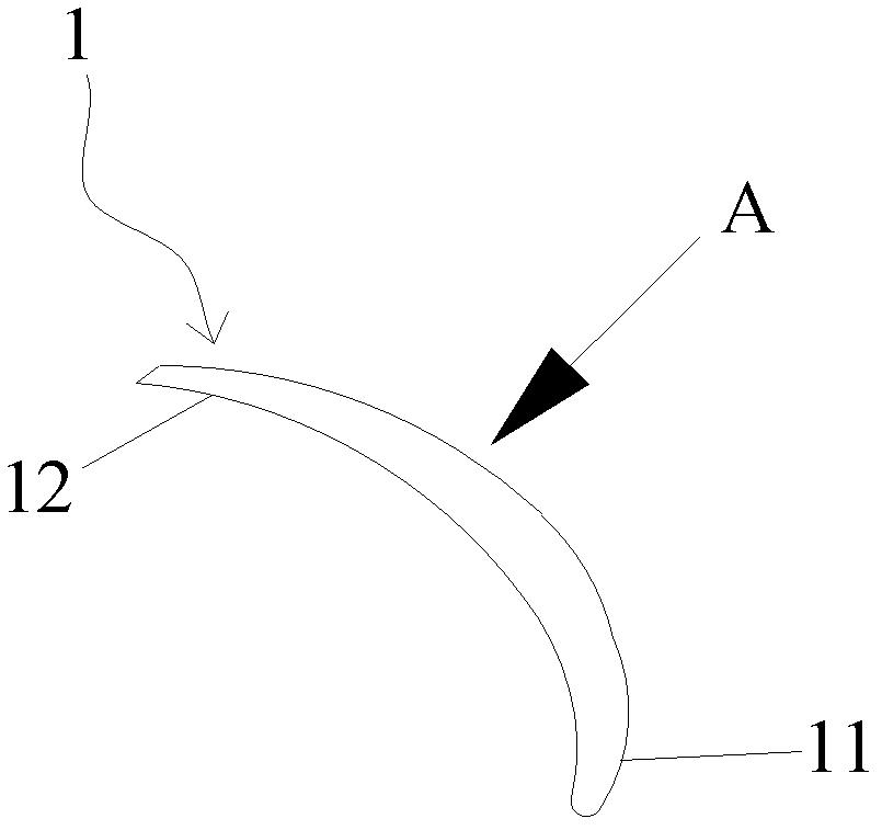
[0023] See Figure 5 and Figure 6 , Figure 5 It is a structural schematic diagram of the blade structure of the centrifugal fan in Embodiment 1 of the present invention; Figure 6 for Figure 5 A schematic diagram of the blade structure of the centrifugal fan in Example 1.

[0024] The blade structure of the centrifugal fan provided in this embodiment includes a blade leading edge 12 and a blade trailing edge 11. The blade trailing edge 11 is a sawtooth structure, and the sawtooth structure includes a tooth groove 111 and a crest 112. The teeth in the sawtooth structure of the blade trailing edge 11 are The ratio of the height a of the groove 111 to the width of the blade 1 is 25%; the angle a of the tooth groove 111 in the sawtooth structure of the blade trailing edge 11 is 60°; the outer surface of the side where the blade trailing edge 11 is located is provided with a small pit 113 ; The shape of the small pit 113 is one or more of circular, square or triangular. The...

Embodiment 2

[0028] The blade structure of the centrifugal fan provided by this embodiment includes a blade leading edge and a blade trailing edge, the blade trailing edge is a sawtooth structure, and the sawtooth structure includes tooth grooves and tooth tops, and the height of the tooth grooves in the sawtooth structure of the blade trailing edge is the same as that of the blade. The width ratio is 30%; the angle a of the tooth groove in the sawtooth structure of the trailing edge of the blade is 90°; the outer surface of the side where the trailing edge of the blade is located is provided with small pits; the shape of the small pits is circular, square or triangular one or more of. In the sawtooth structure, the tooth top is in the shape of a pointed tooth top.

[0029] The leading edge of the blade is a sawtooth structure, and the sawtooth structure includes tooth grooves and tooth tops. The ratio of the height of the tooth grooves in the sawtooth structure of the blade leading edge t...


PUM

PropertyMeasurementUnit
Angleaaaaaaaaaa

Abstract

The invention discloses a blade structure for centrifugal fans, which comprises a front blade edge and a rear blade edge, and the rear blade edge is of a sawtoothed structure. When airflow enters from the front blade edge and passes through the rear blade edge, the vortex of the tail of a blade can be reduced under the function of the sawtoothed structure, at the same time, the original integral airflow is broken up, the disturbance of the airflow is increased, a big vortex which is produced after the airflow passes through the blade can be divided into small vortexes, consequently, the airflow resistance can be effectively decreased, and meanwhile, the vibration and noise of a centrifugal fan can be reduced.

Description

technical field [0001] The invention relates to the field of centrifugal fans, and more precisely refers to a blade structure of a centrifugal fan. Background technique [0002] At present, the blade 1 used in the existing multi-blade centrifugal wind wheel includes the blade leading edge 12 and the blade trailing edge 11. The blade leading edge 12 and the blade trailing edge 11 are all neat and flush shapes. Please refer to Figure 1 to Figure 4 . When the fan is running normally, vortices will be generated when the airflow passes through the trailing edge 11 of the blade, and these vortices will periodically fall off from the trailing edge 11 of the blade, forming a Karman vortex street. This will not only affect the efficiency of the fan, but also generate relatively large vibration and noise. Although the performance of the multi-blade centrifugal fan is now optimized, it is mainly improved from the installation angle of the blade, the change of the inner and outer diam...

Claims


Application Information

Patent Timeline
IPC IPC(8): F04D29/30
Inventor 万忠民陈水荣尹吉成许文明
Owner GUANGDONG CHIGO AIR CONDITIONING
Why Eureka
Try Eureka