
Automatic clutch actuating mechanism and control method thereof

An automatic clutch and actuator technology, which is applied in the direction of non-mechanical drive clutches, clutches, mechanical equipment, etc., can solve problems such as the self-locking ability being greatly affected by the structure, the actuator cannot work, and the motor is highly dependent, achieving long-term stability Efficient work, strong adjustability, fast movement effect

Inactive Publication Date: 2012-08-01
WEICHAI POWER CO LTD
View PDF5 Cites 24 Cited by
  • Summary
  • Abstract
  • Description
  • Claims
  • Application Information

AI Technical Summary

Problems solved by technology

[0010] The actuator of the electric clutch is powered by a motor. After converting the rotary motion into a linear motion through gear meshing transmission, it drives the clutch rod to realize coupling or separation. Its self-locking ability is greatly affected by the structure, and its detachability is poor. , so the entire actuator depends too much on the motor, once the motor has a problem, the entire actuator will not work
[0011] The actuator of the pneumatic clutch is powered by the cylinder, and the cylinder can directly drive the clutch rod through the piston rod to realize the combination or separation. Its structure is simple, the response is fast, and the control is convenient, but the control accuracy is relatively poor.

Method used


Image

  • Automatic clutch actuating mechanism and control method thereof
  • Automatic clutch actuating mechanism and control method thereof
  • Automatic clutch actuating mechanism and control method thereof

Examples


Embodiment Construction

[0046] The core of the invention is to provide an automatic clutch actuator. On the basis of the electric actuator, the actuator adds a cylinder as an auxiliary component, which can be driven by the motor and the cylinder together, or independently driven by the motor or the cylinder, and can work stably and effectively for a long time.

[0047] Another core of the present invention is to provide a control method for controlling the automatic clutch actuator.

[0048] In order to enable those skilled in the art to better understand the solution of the present invention, the present invention will be further described in detail below in conjunction with the accompanying drawings and specific embodiments.

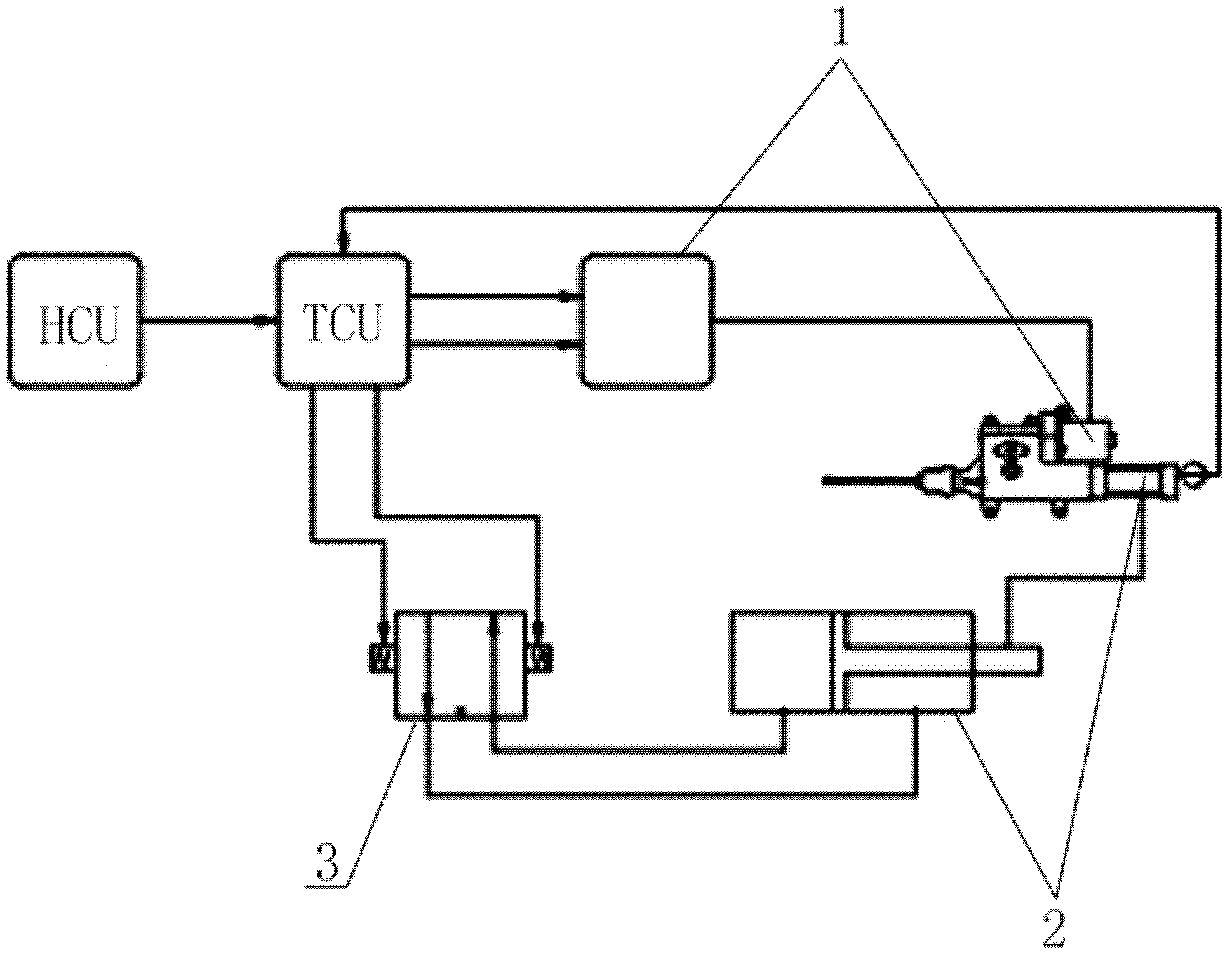
[0049] Please refer to figure 2 , figure 2 It is a structural block diagram of the automatic clutch actuator provided by the present invention.

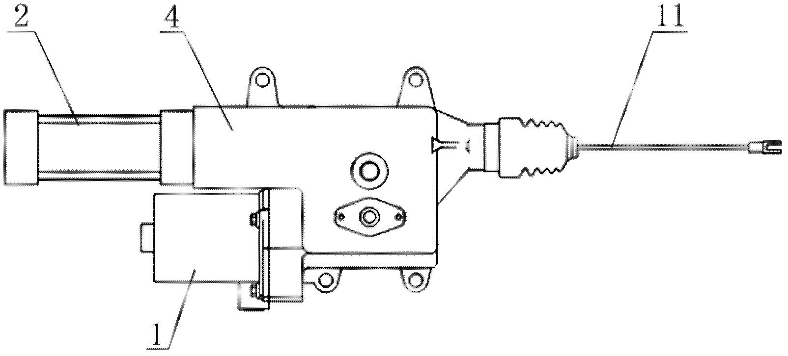
[0050]In a specific embodiment, the automatic clutch actuator provided by the present invention is driven by the motor 1 to r...


PUM


Abstract

The invention discloses an automatic clutch actuating mechanism. The automatic clutch actuating mechanism comprises a motor, a pulling rod and a actuating mechanism controller as well as a cylinder controlled by an electromagnetic valve, wherein the motor is connected with the pulling rod through a transmission part in a transmission way; the piston rod of the cylinder is connected with the pulling rod in a transmission way; the control ends of the motor and the electromagnetic valve are both connected to the actuating mechanism controller; and the actuating mechanism controller is used for controlling the motor and the cylinder to synchronously or independently run. According to the automatic clutch actuating mechanism, the cylinder is configured on the basis of an electric actuating mechanism to serve as an auxiliary element, so that the automatic clutch actuating mechanism can be driven by both the motor and the cylinder or also can be independently driven by the motor or the cylinder, so as to work stably and effectively for long time. The invention further discloses a control method for controlling the automatic clutch actuating mechanism.

Description

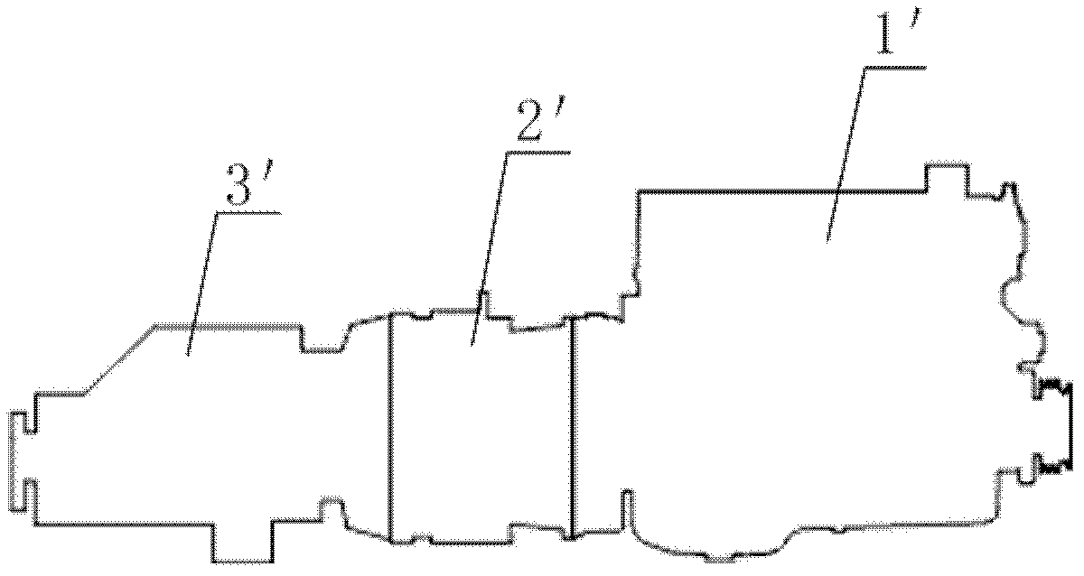
technical field [0001] The invention relates to the technical field of automobile power systems, in particular to an automatic clutch actuator of a parallel hybrid power system. The invention also relates to a control method of the actuator. Background technique [0002] The parallel hybrid system uses the engine and the electric motor to jointly drive the vehicle. The engine and the electric motor belong to two systems, which can independently provide torque to the vehicle transmission system, and can be driven jointly or independently under different road conditions. [0003] Please refer to figure 1 , figure 1 It is a simplified schematic diagram of a typical parallel hybrid power system in the prior art. [0004] As shown in the figure, the parallel hybrid power system is used in a bus. The engine 1' and the motor 2' are coaxially connected in series to drive the vehicle in a mechanically superimposed manner, and can be combined into different power modes. [0005] A...

Claims


Application Information

Patent Timeline
Patent Type & Authority Applications(China)
IPC IPC(8): F16D29/00
Inventor 韩尔樑王朝辉潘凤文刘信奎刘涣东耿丽珍
Owner WEICHAI POWER CO LTD
Learn More